A strip accumulator temporarily stores steel strip between the coil-entry equipment and the forming mill. Its purpose is to separate the timing of upstream coil preparation from the downstream demand for strip.
During coil changeover and end welding, the inlet section may stop feeding new material. The forming mill can continue drawing strip from the accumulator for as long as sufficient usable storage remains. This article explains how that buffer is built, consumed and replenished.
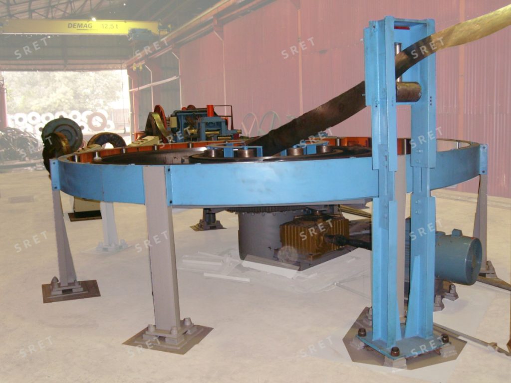
Steel arrives at the entry section in separate coils, while the forming mill requires a continuous strip feed during production. When one coil ends, the next coil must be prepared and joined to it.
The uncoiler, flattener and shear end welder perform these entry operations. The accumulator holds strip that has already passed through the joining section, allowing the forming mill to draw from storage while upstream work takes place.
The accumulator does not eliminate coil changeover or welding time. It provides a temporary reserve that can cover those operations when the available storage is sufficient.
The amount of strip in the accumulator depends on the difference between the inlet and outlet feed rates:
This relationship explains why the entry equipment needs a replenishment phase after coil joining. Feeding only at the same speed as the forming mill maintains the remaining reserve; it does not rebuild the strip that was consumed during the interruption.
The entry section feeds strip into the accumulator faster than the forming mill withdraws it. The difference between the two rates builds the stored length within the permitted operating capacity.
The exact movement of the loops and supporting rolls depends on the accumulator design. The control system coordinates filling and responds when the permitted storage limit is reached.
When inlet feeding pauses for coil changeover, shearing or end welding, the forming mill continues pulling strip from storage. The available reserve decreases throughout this period.
The accumulator can bridge the interruption only while sufficient strip remains. If the entry operation takes longer than the reserve can cover, downstream operation must respond to the low-storage condition.
Once the next coil has been joined and inlet feeding resumes, the entry section rebuilds storage by feeding faster than the outlet demand.
Replenishment must remain within the machine’s permitted fill-in speed and the operating limits of the connected entry equipment.
After replenishment, inlet and outlet operation can be coordinated to maintain the required storage level until the next coil change.
The complete cycle therefore consists of building a reserve, drawing from it during an inlet interruption, and restoring it afterward.
Two quantities are particularly important: the usable stored strip length and the downstream strip speed. At a constant outlet speed, the approximate buffer time is:
Buffer time = usable stored strip length ÷ outlet strip speed.
Using length in metres and speed in metres per minute gives the result in minutes. The usable reserve should reflect the storage that can actually be withdrawn within the permitted operating limits, rather than simply the machine’s maximum nominal capacity.
The required reserve must cover the complete inlet interruption, including coil changeover, end preparation, welding and restarting. A higher downstream speed consumes the same reserve more quickly.
The product series includes tabletop, horizontal roller and horizontal spiral accumulators. These names describe equipment arrangements.
Variable-loop and fixed-loop storage describe how the loops are managed within the relevant machine design:
These two descriptions should not be treated as a complete replacement for the equipment-type classification. The applicable loop arrangement and operating sequence must be confirmed for the selected model.
Likewise, tube diameter alone does not define the required accumulator. Strip dimensions, storage requirements, fill-in speed and the equipment’s operating range must be considered together.
In the series described here, the strip enters from the outer side and exits from the center. Guide rolls and the accumulation structure support its movement through storage.
At the outlet, the strip passes through the exit arrangement and de-twist guide stands before entering the forming mill. These components guide the strip into the orientation required by the downstream equipment.
The entry and exit paths form part of the machine design. Their layout should be checked against the proposed installation rather than described as freely adjustable in every configuration.
Empty and full storage detection help the control system manage the accumulator within its permitted range. Alarms notify operators of storage conditions that require attention.
The horizontal spiral configurations described in the product range provide stop, high-speed fill-in, mill-synchronized speed and jog modes. Centralized chain drive or separate individual drives may be used according to the configuration.
Automatic monitoring supports the storage cycle, but it does not make the accumulator an unlimited reserve. Operators still need to respond to alarms and monitor the coordinated operation of the entry equipment and forming mill.
The accumulator must guide and support the strip during both filling and withdrawal. Roll alignment, guide condition and the suitability of the strip path are therefore important operating considerations.
The equipment should not be described as guaranteeing zero scratching, folding or jamming under all conditions. Strip handling also depends on correct setup, incoming material condition and operation within the specified range.
For coated or appearance-sensitive strip, the handling arrangement and contact surfaces should be checked against the production requirements.
It can allow the forming mill to continue running while the inlet section changes and joins coils, provided the usable reserve covers the interruption. It does not eliminate the upstream work itself.
The forming mill continues consuming strip while the reserve is being restored. The inlet therefore needs to exceed the outlet rate to increase the stored length.
No. Coil-change frequency depends on how much strip each coil supplies and how quickly the line consumes it. More usable storage provides a larger buffer for handling the changeover; it does not change the amount of material in a coil.
Not necessarily. Tabletop describes an equipment arrangement, while variable-loop describes a storage method. The terminology should follow the actual configuration.
The accumulator can no longer cover an inlet interruption. Low-storage detection and the line’s control response must manage the condition before the permitted reserve is exhausted.
No. Fill-in speed is model-specific. It must be checked together with strip width, thickness, storage capacity and the limits of the connected entry equipment.
For equipment types, model-specific strip ranges, storage capacities and fill-in speeds, refer to the strip accumulator product page.