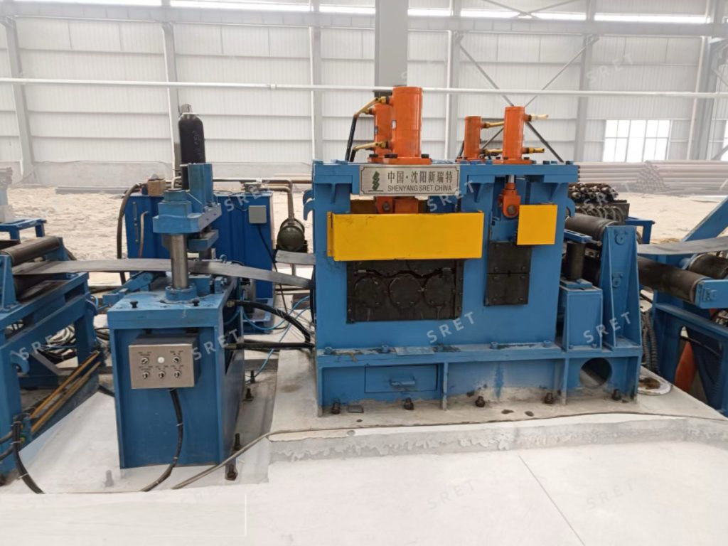
A strip-end flattener prepares the head and tail of a steel coil before shearing and butt welding. Its place in an ERW tube mill line is clearly defined, but the details of its configuration should not be assumed from a general equipment description.
Questions often arise around material suitability, roll arrangement, alignment adjustment and feeding speed. A useful technical review separates what the published equipment data confirms from what must be agreed for the proposed application.
This article focuses on those specification checks. For equipment construction and published model ranges, refer to SRET’s strip-end flattener product page.
A statement such as “a flattener is required above φ89” should not be used as a universal selection rule. The product data lists different strip-width and thickness ranges across the equipment models.
For an ERW Tube Mill project, provide the incoming strip specifications rather than relying only on the finished-tube diameter.
The review should identify:
The frequently used products deserve attention alongside the extremes of the range. A proposal should explain the supported operating combinations, not simply repeat separate maximum width and thickness figures.
A dimensional range does not, by itself, establish suitability for every steel grade.
Descriptions such as carbon steel, alloy steel and stainless steel cover different material requirements. Likewise, naming grades such as Q235 or Q355 does not confirm that the same equipment settings apply to all products.
When requesting a tube mill machine proposal, provide the actual grades and relevant material information for engineering review. Ask the supplier to identify which materials form the basis of equipment selection.
If several grades are planned, the technical proposal should distinguish the confirmed scope from materials that require additional assessment. Avoid presenting a general equipment description as approval for every material within the listed dimensions.
SRET’s published equipment description includes two arrangements:
| Arrangement | Movable Upper Rolls | Stationary Lower Rolls |
| Five-roll | 2 | 3 |
| Seven-roll | 3 | 4 |
However, the model table does not offer both arrangements throughout the range. Some models list five- or seven-roll structures, while others list five rolls only.
The useful question is therefore not whether seven rolls are always better. It is whether the proposed structure is appropriate for the specified strip and preparation requirement.
For an ERW tube mill machine quotation, ask the supplier to confirm:
Do not assume that a larger thickness range automatically requires seven rolls or that a five-roll machine is unsuitable for heavier strip.
Different mechanisms perform different tasks.
The published flattener description identifies electrically adjustable vertical rolls at the entrance for centering the strip. It separately describes hydraulically actuated upper flattening rolls that move downward to apply pressure.
These functions should not be combined into a statement that the machine has “standard hydraulic center alignment.”
The proposal should identify the adjustment method for each mechanism. If manual, motorized or hydraulic alternatives are offered, their availability should be stated explicitly rather than inferred.
It is also useful to confirm which adjustments require operator input and which actions form part of the machine sequence. Powered adjustment does not automatically mean that the machine detects and corrects every positioning condition without operator involvement.
The roll-drive arrangement is another detail that should be stated by configuration.
SRET’s general description includes arrangements in which the upper rolls are driven or both upper and lower rolls are driven. A project article should therefore not describe passive lower rolls as a universal standard.
Request a clear distinction between:
This helps prevent mechanical movement, pressure application and rotational drive from being treated as the same function.
Similarly, specific roll materials, heat treatments and component grades should be included only when confirmed in the equipment documentation.
The product description includes proportional pressure adjustment for the flattening hydraulic cylinder. The technical proposal should explain how this function is implemented in the supplied machine.
Useful questions include:
Pressure adjustment supports the flattening operation, but it should not be presented as an unconditional guarantee of identical results across all materials and thicknesses.
The acceptance procedure should define the required strip-end condition and the circumstances under which it will be assessed.
The feeding duty of the flattener is different from the production duty of the forming and welding sections.
When reviewing a tube mill line layout, do not assign the maximum production speed to every entry machine. The published flattener table lists model-specific feeding speeds.
The review should explain how the flattener advances the prepared strip toward the shear end welder and how the entry equipment coordinates during coil-end preparation.
Confirm the relevant operating modes, control interfaces and operator tasks. Where timing matters, review the complete preparation and joining sequence rather than considering feeding speed alone.
For a new installation or retrofit, the proposal should establish the physical interfaces as well as the processing range.
| Review Item | Information to Agree |
| Feeding direction | Required strip travel direction |
| Working height | Relationship with adjacent equipment |
| Installation space | Machine position and access requirements |
| Upstream interface | Transfer from the uncoiler |
| Downstream interface | Transfer toward the shear end welder |
| Controls | Signals, operating sequence and operator responsibilities |
| Acceptance | Strip specifications and inspection method |
Do not assume that both feeding directions or every interface arrangement are included as standard. Confirm the required configuration in the agreed layout.
A technical review should turn general descriptions into a defined supply scope. It should confirm the strip requirements, roll structure, drive arrangement, adjustment functions and equipment interfaces before an order is finalized.
This article addresses those confirmation points rather than replacing the model table. For published strip ranges, feeding speeds and roll options, see SRET’s flattener specifications and model information.