Preparing a coil end for shearing and butt welding involves more than pressing it between rolls. The strip must first be positioned at the entrance, guided into the roll assembly and advanced under the specified working conditions.
In an ERW tube mill line, a strip-end flattener coordinates these tasks to prepare the head and tail of the coil. Its function should be distinguished from finished-tube straightening or broader strip-shape correction processes.
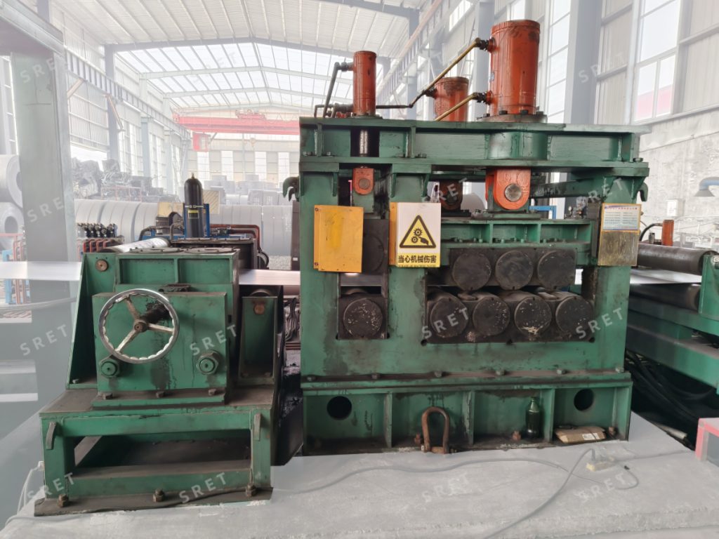
The entrance alignment, pinching and flattening sections perform different tasks:
Understanding this division helps avoid describing every part of the machine as performing the same leveling function.
The original equipment description specifies electrically adjustable center-aligning vertical rolls at the flattener entrance. These rolls adjust the position of the strip arriving from the uncoiler.
Entrance alignment prepares the strip for the feeding and flattening sections. It should not be described as automatic correction of every strip-shape defect or as a guarantee against edge damage.
The technical specification should identify how the rolls are adjusted and which actions require operator input.
After the clutches are engaged, motor-driven pinching rolls guide the strip toward the flattening rolls.
Their role is to grip and advance the material. This feeding function should not automatically be described as an independent tension-control system.
For a tube mill line, the proposal should explain how the pinching section coordinates with the roll assembly and the downstream receiving equipment.
Once the strip is presented to the flattening section, the hydraulically actuated upper rolls move downward to apply pressure.
The original equipment information describes proportional pressure adjustment for the leveling cylinders. The supplied controls should define how the required pressure is selected and adjusted for the strip being processed.
Do not assume that proportional adjustment includes automatic thickness measurement or material identification unless those functions are explicitly supplied.
The driven rolls reduce coil-end curvature while moving the strip toward the shear end welder.
The original description includes configurations with upper-roll drive or with both upper and lower rolls driven by an inverter-controlled AC motor. The applicable drive arrangement should be confirmed for the selected machine.
Hydraulic roll movement and rotational drive are separate functions. A roll can move vertically for adjustment, rotate to advance the strip, or perform both actions according to the design.
The supplied equipment description identifies two structures:
The term “fixed” describes the lower-roll mounting position here; it should not be interpreted as meaning that the rolls cannot rotate.
The roll count also does not establish which rolls are driven. For a tube mill machine proposal, confirm the layout, movement and drive arrangement separately.
After preparation, the coil end is fed toward the shear end welding machine for trimming and butt welding.
Flattening prepares the end condition, but it does not replace the downstream alignment, shearing and welding operations. The completed joint depends on those stages as well.
For an ERW tube mill machine, the interface review should include the strip path, working height, feeding controls and responsibilities of the receiving equipment.
For model-specific dimensions, feeding speeds and listed roll configurations, see SRET’s strip-end flattener product page.
Their primary role is to position the strip at the entrance. Flattening is performed by the dedicated roll assembly.
The supplied description confirms feeding and guidance. Any additional tension-control function should be identified separately in the technical proposal.
No. The original description includes different drive arrangements. Confirm the configuration for the selected model.
The equipment discussed here prepares coil heads and tails. Broader claims about camber correction, stress removal or complete strip leveling should not be assumed from this function.
The prepared coil end moves toward the shear end welder for trimming and joining to the adjacent coil end.