The difference between a five-roll and seven-roll strip-end flattener starts with the roll arrangement, but it does not end there. Movable-roll positions, rotational drive and hydraulic adjustment are separate features that should be identified in the equipment specification.
In an ERW tube mill line, the flattener prepares coil heads and tails before end shearing and butt welding. This article explains how to read the five-roll and seven-roll configurations described in SRET’s equipment information without assuming that one arrangement is universally better.
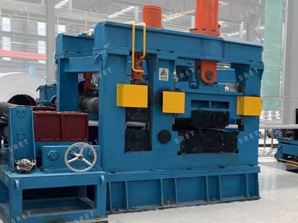
The supplied equipment description identifies the following arrangements:
| Configuration | Movable Upper Rolls | Lower Rolls in Fixed Positions | Total Rolls |
| Five-roll structure | 2 | 3 | 5 |
| Seven-roll structure | 3 | 4 | 7 |
The seven-roll structure adds one upper and one lower roll to the arrangement. However, the roll count alone does not define the machine’s complete processing capability, drive system or adjustment method.
The appropriate configuration should be confirmed against the required strip specifications and the available equipment design.
Movable Rolls and Driven Rolls Are Not the Same
A movable upper roll can change position to establish the working arrangement and apply pressure. A driven roll receives rotational power from the machine’s drive system.
These descriptions answer different questions. The statement “three movable upper rolls” does not automatically mean “three independently driven upper rolls.”
SRET’s original equipment description includes arrangements in which either the upper rolls or both the upper and lower rolls are driven. The applicable configuration should therefore be confirmed separately from the total number of rolls.
Likewise, a lower roll in a fixed mounting position should not automatically be described as a non-rotating roll. Its mounting position and its rotational drive are separate characteristics.
The flattening rolls operate together with entrance alignment and strip-feeding equipment. In the described arrangement, the sequence includes:
The entrance aligning rolls, pinching rolls and flattening rolls have different functions. They should not be combined into a single description of “automatic leveling.”
The supplied product information describes proportional pressure adjustment for the leveling cylinders. The intended function is to adjust the applied flattening force for the strip being processed.
When reviewing the controls, confirm how the pressure setting is established. The technical documentation should explain whether settings are entered by the operator, selected from a recipe or adjusted through another specified control method.
A proportional hydraulic function should not be expanded into claims about automatic material identification or thickness measurement unless those functions are included in the equipment.
The supplied data do not support a universal ranking based only on roll count.
Some models are listed with five- or seven-roll configurations, while others are listed with five rolls. This means availability must be checked by model rather than assumed across the complete range.
For example, the published table lists five- or seven-roll arrangements for JP32 through JP165, while JP219 through JP711 are listed with five-roll arrangements.
These entries show the offered structures. They do not, by themselves, establish that one configuration is more accurate or suitable for every material.
Before comparing five-roll and seven-roll proposals for a tube mill line, provide:
Ask the supplier to identify the proposed roll layout, driven-roll arrangement, hydraulic adjustment functions and operating limits for those requirements.
For a tube mill machine processing several specifications, the review should cover the intended product range rather than only one demonstration condition.
| Item | What to Confirm |
|---|---|
| Roll layout | The number and positions of upper and lower rolls. |
| Roll movement | Which rolls move for adjustment and how they are actuated. |
| Roll drive | Which rolls receive rotational power and the applicable drive arrangement. |
| Pressure control | How flattening pressure is set and adjusted. |
| Operating range | The supported strip-width, thickness and material combinations. |
| Feeding | The specified speed and interface with the next process. |
If roll material, heat treatment or motor power is important to the project, include those details in the specification for the selected machine. They should not be assumed from the roll count.
Not necessarily. Three movable upper rolls describe the layout and adjustment arrangement. The rotational drive must be confirmed separately.
No such conclusion should be drawn from the word “fixed.” In this description, it refers to the mounting position. The drive arrangement is a separate specification.
The supplied model table does not show it for every model. Confirm availability and suitability for the proposed equipment.
No. The incoming strip range, material requirements and entry-process arrangement should be reviewed when specifying the flattener for an ERW tube mill machine.
No. It prepares the strip ends for the next operation. Shearing, joint positioning, clamping and welding remain separate parts of the joining process.
For model-specific strip dimensions, feeding speeds and listed roll configurations, see SRET’s strip-end flattener product page. The final configuration should be confirmed for the proposed ERW tube mill line.