A strip-end flattener prepares the head and tail of a steel coil before end shearing and butt welding. In an ERW tube mill line, it forms part of the entry equipment, receiving strip from the uncoiler and feeding the prepared end toward the shear end welder.
Its purpose is to reduce coil-end curvature and make the strip easier to position for the next operation. It should not be confused with equipment used to straighten finished tubes.
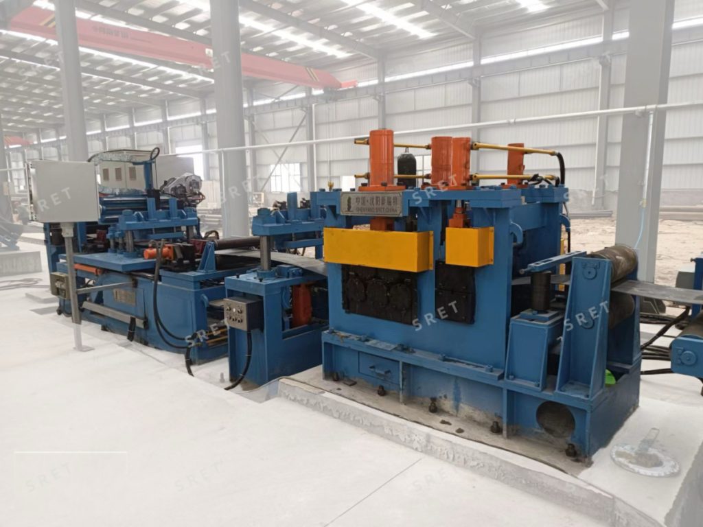
Coil heads and tails can retain curvature that makes handling and positioning more difficult. Flattening prepares these sections before they are trimmed and joined.
This preparation supports the subsequent joining process, but it does not guarantee butt-weld quality on its own. Shearing, alignment and welding must also meet the requirements of the application.
In the arrangement described in SRET’s original equipment specification, electrically adjustable vertical rolls position the incoming strip at the flattener entrance. They align the strip before it enters the pinching and flattening sections.
The motor-driven pinching rolls grip and guide the strip into the flattening section. The original specification describes a clutch-engaged drive arrangement.
The proposed equipment specification should identify the pinching-roll configuration and how its operation is coordinated with the surrounding entry equipment.
Hydraulically actuated upper rolls move downward to apply pressure against the strip and lower rolls. The roll assembly reduces coil-end curvature while advancing the strip toward the next operation.
Drive arrangements can differ. The original equipment description includes versions with upper-roll drive or with both upper and lower rolls driven. The applicable arrangement should be confirmed for the selected model.
The hydraulic system operates the upper rolls, while the electrical controls manage the machine’s operating sequence and drive speed. Inverter-controlled AC motors provide adjustable feeding speed.
Where proportional hydraulic pressure adjustment is specified, the proposal should explain how the pressure is set and controlled. Adjustable pressure should not automatically be described as material detection or closed-loop automatic compensation.
The original equipment range describes two roll arrangements:
The number of movable rolls does not, by itself, establish which rolls are driven. Roll movement and roll drive should be identified separately in the technical specification.
A seven-roll arrangement should not be presented as universally better than a five-roll arrangement. Selection should be based on the intended strip range and required preparation conditions. Availability also varies by model.
The exact sequence and operator responsibilities should be confirmed for the supplied equipment rather than assumed from this general description.
Selection starts with the incoming strip requirements. Provide the material specification, minimum and maximum widths, thickness range and expected coil-end condition.
When reviewing a tube mill machine proposal, ask the supplier to confirm:
For an ERW tube mill machine, the flattener’s feeding speed should be specified separately from the production speed of the forming and welding sections. The required entry-equipment sequence should be reviewed as part of the complete line.
A fixed tube-diameter threshold should not be used as a universal rule. The supplied model range includes several strip-width and thickness ranges. Selection should follow the actual strip and entry-process requirements.
Do not assume that a dimensional range applies equally to every material. Provide the actual grades and relevant properties so that the supplier can confirm the proposed equipment’s suitability.
Not automatically. The arrangement should be evaluated for the intended application, including the strip range, pressure adjustment and drive configuration.
No. Flattening prepares the coil ends, but the completed joint also depends on the downstream shearing, alignment and welding operations.
Confirm the strip specifications, available space, working height, feeding direction and equipment interfaces. The proposed layout should show how the flattener connects with the existing entry section.