In an ERW tube mill line, the flattener prepares the head and tail of steel coils before shearing and butt welding. Installed after the uncoiler and before the shear end welder, it reduces the curvature remaining in the coil ends so that they can be positioned and joined more consistently.
Understanding this process helps explain the role of the flattener in the entry section: it prepares the strip ends for joining, rather than forming the tube or providing strip storage during a coil change.
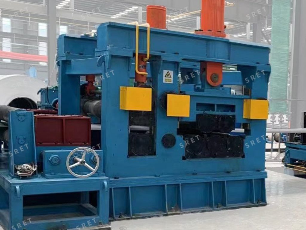
Steel strip can retain curvature after it is unwound from a coil. This residual curvature, commonly called coil set, can make the head and tail difficult to position at the shearing and welding station.
The flattener reduces this curvature before the strip ends reach the shear end welder. Flatter ends are easier to guide, clamp and align for trimming and butt welding. The resulting joint connects the outgoing coil to the incoming coil for subsequent processing.
Flattening is therefore part of strip-end preparation. Continuous operation during coil changeover also depends on the shear end welder, strip accumulator and coordinated operation of the entry section.
The flattener combines mechanical, hydraulic and electrical systems. Three mechanical assemblies carry out the main strip-handling functions.
Electrically adjustable vertical centering rolls guide the strip coming from the uncoiler. Their purpose is to correct its lateral position before it enters the pinch rolls and leveling section.
Centering and flattening perform different tasks. The centering device positions the strip across the machine width, while the leveling rolls reduce curvature along the strip.
The motor-driven pinch rolls feed the strip into the leveling section after the clutches engage. They provide controlled movement during coil-head feeding and coil-tail preparation.
The pinch-roll unit advances the strip; the leveling rolls perform the flattening action. Keeping these functions distinct makes the operating sequence easier to understand.
The leveling section uses upper and lower rolls arranged to bend the strip alternately as it passes through the machine. This action reduces coil-set curvature in the head and tail.
Hydraulic cylinders lower the movable upper rolls into the working position. Depending on the configuration, either the upper rolls or both the upper and lower rolls are driven by inverter-controlled AC motors to process and advance the strip.
The flattener configurations described here use either five or seven leveling rolls:
In this description, “fixed” refers to the mounting position of the lower rolls, not to whether they rotate.
The additional rolls in a 7-roll arrangement provide more bending stages. However, roll count alone does not determine the leveling result. Strip thickness, material strength, incoming curvature, roll geometry and operating adjustments also need to be considered.
A 7-roll arrangement should therefore not be treated as a universal requirement for larger tube sizes or as an automatic replacement for a 5-roll machine. The appropriate configuration depends on the strip-processing requirements and the equipment design.
The hydraulic system positions the upper leveling rolls and applies the required working force. Proportional pressure adjustment allows the leveling force to be adapted to different strip thicknesses within the machine’s operating range.
Pressure adjustment and roll positioning work together. The aim is to reduce coil-end curvature sufficiently for the next operation, rather than simply applying the highest available pressure.
Inverter-controlled AC drives regulate strip movement through the machine. The hydraulic and electrical systems must operate together so that the strip is fed through the engaged roll set and delivered to the shearing and welding station.
The entry flattener prepares coil ends for shearing and joining. Its function should be distinguished from that of the other equipment in an ERW tube mill line:
The flattener does not replace the accumulator, and flatter coil ends alone do not guarantee an uninterrupted production cycle. Each machine performs a separate task within the entry section.
It reduces curvature in the coil head and tail before trimming and joining. This helps the strip ends sit more consistently in the positioning and clamping area of the shear end welder.
Centering corrects the lateral position of the strip as it enters the machine. Flattening reduces the residual curvature of the coil ends through the action of the leveling rolls.
Not necessarily. A 7-roll arrangement provides additional bending stages, but the result also depends on strip properties, roll geometry and machine settings. The configuration should be matched to the intended operating range.
The leveling cylinders use proportional hydraulic pressure adjustment to adapt the working force. Pressure settings and upper-roll positions must suit the strip specifications and the required coil-end condition.
Not by itself. The flattener prepares the coil ends, the shear end welder joins them, and the accumulator provides stored strip while the joining operation takes place.
For available models, strip-processing ranges, operating speeds and roll configurations, see the flattener product page.