A variable-loop strip accumulator stores strip between the entry section and the forming mill. Its purpose is to bridge interruptions in incoming strip supply while the mill continues consuming material.
For an ERW tube mill line, the important planning question is not simply how many loops the accumulator can hold. It is whether the available strip reserve can cover the required interruption—and whether that reserve can be restored before it is needed again.
This article focuses on that operating balance. For equipment types, published model ranges and available operating arrangements, see SRET’s horizontal spiral strip accumulator.
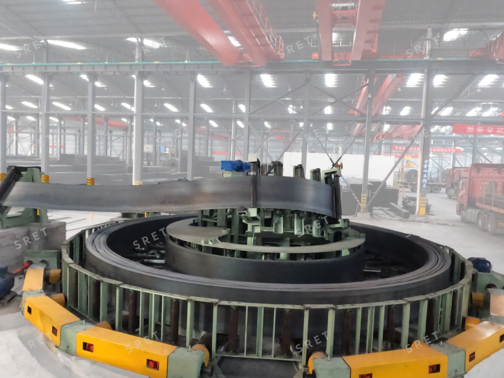
The accumulator should be reviewed against the period during which incoming strip is unavailable.
That period should not automatically be treated as welding time alone. Depending on the entry-section arrangement, it may also include the required strip positioning, end preparation, inspection and release activities.
Before assessing storage requirements, define:
For a tube mill line, this creates a clearer basis for storage planning than a general request for “continuous production.”
Use an agreed interruption duration rather than assuming that every coil change will take exactly the same time.
At a constant strip withdrawal speed, the basic strip length consumed during an interruption is:
Lconsumed=vout×tinterruption
Where:
This is a material-balance relationship, not a complete equipment-sizing rule. The project must also establish the permitted operating reserve, control limits and applicable allowances.
Use strip withdrawal speed at the accumulator outlet. Do not substitute another downstream speed without confirming that it represents the same strip consumption.
If the operating speed changes during the interruption, assess the strip consumed across the relevant operating stages rather than applying one unverified maximum or average value.
A published storage figure and the strip reserve available at a particular moment are not necessarily the same.
Before coil-end preparation begins, the accumulator may not be at its permitted upper operating level. Some strip may also need to remain within the machine’s approved operating range.
The practical question is:
How much strip can be withdrawn from the actual starting condition before the agreed lower operating limit is reached?
Confirm the following with the supplier:
| Storage Item | Point to Confirm |
| Published capacity | What the stated storage figure represents |
| Operating limits | The approved upper and lower storage conditions |
| Starting reserve | The required storage condition before an interruption |
| Available buffer | The strip that can be supplied within those limits |
| Detection signals | How storage conditions are indicated and acted upon |
SRET’s model table gives storage ranges alongside strip dimensions and fill-in speeds. Treat these as model-selection information, not as proof that every listed capacity applies to every product and operating condition.
Covering one interruption is only part of the review. The accumulator must also recover the consumed reserve during subsequent operation.
The basic storage balance is:
dL/dt = v_in – v_out
This means:
For an idealized period with constant speeds, where v_in > v_out, the time required to restore a given strip length is:
t_recovery = L_restore / (v_in – v_out)
Actual recovery also depends on the permitted speed profile, acceleration, control sequence and material conditions.
A quoted maximum fill-in speed is therefore not the same as the net storage recovery rate while the mill is running.
A storage arrangement should be assessed over repeated production cycles, not only one successful changeover.
The review should establish whether sufficient reserve can be restored before the next interruption begins.
Useful questions include:
For a tube mill machine operating across several products, these conditions may differ between production schedules.
Assess representative operating cases, including the combinations that place the greatest demand on buffer duration and recovery. Do not assume that one demonstration covers the entire product range.
Finished tube size alone does not provide a complete accumulator specification.
Provide the actual strip width, thickness, material information and required operating conditions. These should be reviewed together with storage and fill-in requirements.
| Input | Why It Must Be Defined |
| Strip width and thickness | Establish the material dimensions to be handled |
| Material specification | Provides the basis for application review |
| Required withdrawal speed | Defines strip consumption during operation |
| Entry interruption | Defines the period the reserve must cover |
| Required operating reserve | Establishes the intended buffer condition |
| Available fill-in conditions | Defines how the reserve can be restored |
| Product changes | Identifies additional conditions requiring review |
Do not assume that maximum strip dimensions, maximum storage and maximum fill-in speed are available simultaneously.
The proposed operating envelope should be confirmed for the selected configuration.
Storage monitoring should be reviewed together with the actions it enables or prevents.
The product page identifies empty and full storage detection, alarms and remote monitoring. Project documentation should explain how those functions interact with the entry section and forming mill.
For each relevant condition, confirm:
Also distinguish operating modes from automatic responses. A machine supporting high-speed fill-in, synchronized speed and jog operation does not, by that description alone, define every transition or interlock.
Those details belong in the agreed control description and operating documentation.
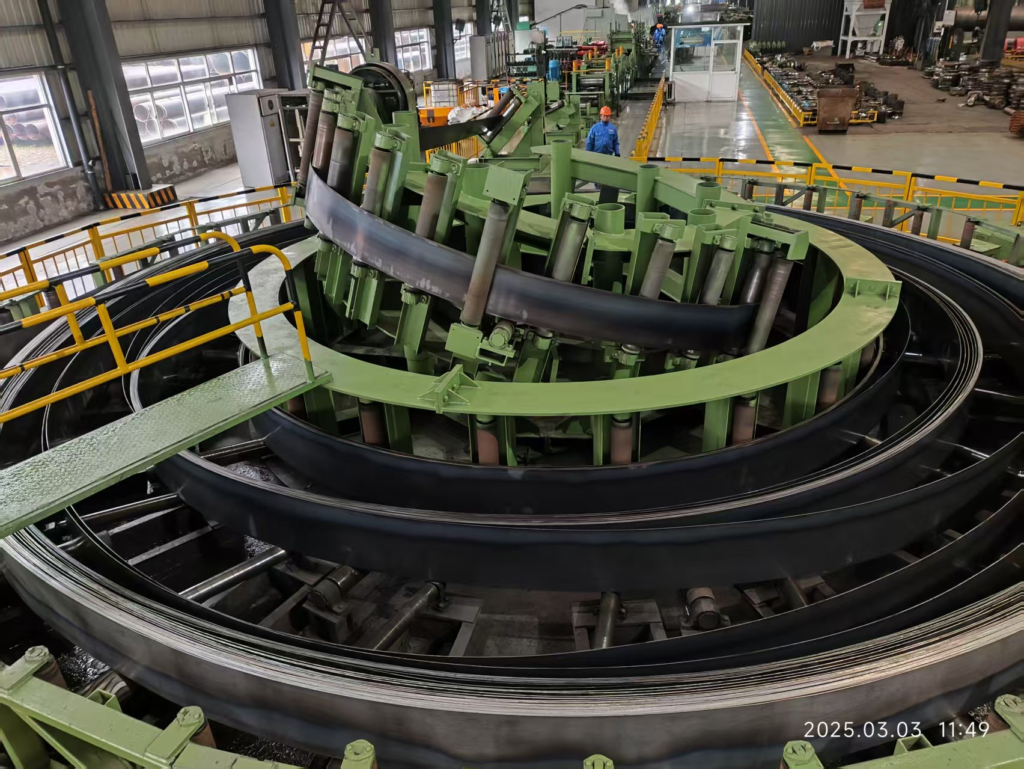
Commissioning should demonstrate the agreed buffer function under stated conditions rather than rely only on a general observation that the accumulator runs.
An acceptance scenario should record:
The test scope should be agreed before commissioning and performed under the supplied operating and safety procedures.
Where several production conditions are proposed, identify which have been demonstrated and which remain subject to further confirmation.
Matching a variable-loop strip accumulator to an ERW tube mill requires more than checking a storage figure.
The review should connect interruption duration, strip consumption, available reserve and replenishment rate across repeated operating cycles.
With those conditions defined, model selection and acceptance can focus on the actual buffer requirement—while equipment construction, drive arrangement and monitoring scope remain tied to the selected configuration.