How long can a tube mill continue running while the entry section prepares and joins the next coil? The answer depends on the available strip reserve, the mill’s operating speed and the time before entry feeding resumes.
A strip accumulator separates intermittent coil-end joining from downstream production by temporarily storing strip. Its capacity should therefore be reviewed as an operating reserve, not simply as a number in a machine specification.
This article explains how storage, joining time and replenishment speed work together in an ERW tube mill line.
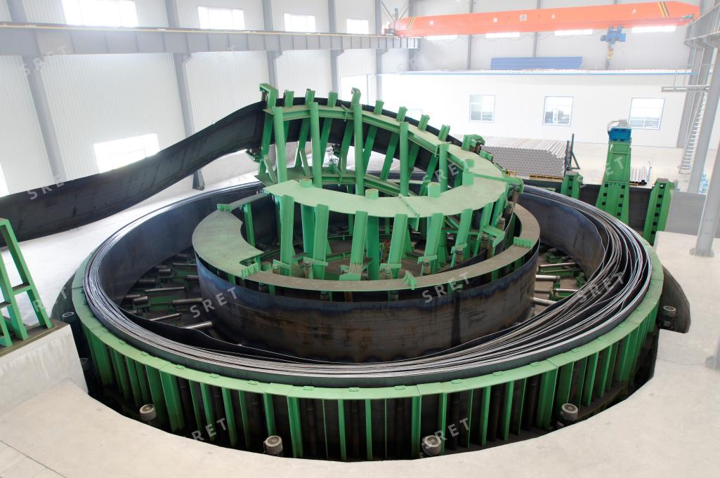
During normal feeding, strip enters the accumulator and is withdrawn toward the forming mill. When entry feeding stops for coil-end preparation and joining, the downstream mill draws from the stored reserve.
After the connection is completed, entry feeding resumes. To rebuild the reserve while the mill continues running, the inlet must supply strip faster than the outlet consumes it.
The accumulator does not eliminate the joining operation. It provides time for that operation to take place without immediately interrupting downstream strip supply.
Stored strip length increases when more strip enters than leaves. This is the replenishment condition, subject to the equipment’s permitted capacity and operating limits.
Under steady conditions, the reserve remains approximately constant when the incoming and outgoing strip speeds are equal.
The reserve decreases when the mill withdraws strip faster than the entry section supplies it. If inlet feeding stops completely, the available reserve supplies the entire downstream requirement for that period.
For a simplified case with constant mill speed and no inlet feeding, the strip consumed during the interruption is:
Required strip length = mill speed × interruption time
Use compatible units. If speed is expressed in metres per minute, time must be expressed in minutes.
For example, a mill running at 60 m/min consumes 120 m of strip during a two-minute interruption in entry feeding.
This is an illustrative material-balance calculation, not a recommended accumulator capacity. Final selection must also consider the usable reserve, operating limits and the agreed allowance for variation in the joining cycle.
Welding travel is only one part of the coil-joining operation. Depending on the supplied equipment and operating procedure, the interruption may also include:
Some preparation may occur before entry feeding stops. The relevant time is the actual period during which the entry section cannot supply the strip required by the downstream mill.
When reviewing a shear end welder’s cycle-time figure, confirm which actions are included before using it for accumulator selection.
A published storage figure should be checked against the proposed application. Ask whether it describes nominal storage, usable discharge length or another defined capacity condition.
The reserve available at the start of joining also matters. An accumulator that has not been sufficiently replenished may provide less operating time than its maximum capacity suggests.
For a tube mill line proposal, confirm:
A high inlet speed does not become reserve at the same rate while the mill is also consuming strip. Under steady conditions, the net replenishment rate is the inlet speed minus the outlet speed.
For example, if strip enters at 100 m/min while the mill withdraws 60 m/min, the reserve increases at 40 m/min. Restoring 120 m would take three minutes at those constant speeds.
This simplified example excludes acceleration and other operating transitions. The actual replenishment sequence must follow the equipment’s specified limits.
When assessing a tube mill machine proposal, therefore, review storage capacity and fill-in capability together. Enough reserve for one interruption does not establish that it can be rebuilt before the next one.
The exact structure varies by accumulator type. In the horizontal arrangement described for SRET’s equipment, the main functions include:
These functions should not be treated as interchangeable. Storage capacity comes from the complete accumulation arrangement, while the central exit track and outlet guides manage strip withdrawal and orientation.
The technical proposal should define how filling, reserve monitoring and downstream withdrawal are coordinated.
Review the supplied empty and full detection functions, alarms, operating modes and interfaces with adjacent entry equipment. If hydraulic or electrical systems are shared, identify that arrangement explicitly in the supply scope.
Do not assume that a shared system automatically provides a particular space saving, tension performance or level of automation.
Before selecting a strip accumulator for an ERW tube mill machine, provide:
For model-specific strip ranges, listed storage capacities and fill-in speeds, see SRET’s strip accumulator product page.
No. It provides a storage reserve. Mill speed must also remain within the capabilities of the complete production line.
Only if it represents the complete relevant interruption, which should not be assumed. Confirm the time from loss of adequate inlet supply to its restoration.
No. Under steady conditions, equal speeds maintain the reserve approximately constant. Replenishment requires inlet supply to exceed outlet consumption.
Not by itself. Review the net replenishment rate, the permitted operating conditions and the actual time available between joining events.
It supports continued strip supply during a defined entry interruption. The usable reserve, mill speed and actual joining sequence must be compatible.