An uncoiler receives and supports a steel coil before releasing strip toward the flattener or the next process. However, selecting the machine is only part of preparing the entry section. The project must also establish how coils arrive, how the strip head is presented and how the equipment returns to a ready condition for the next coil.
For an ERW tube mill line, these interfaces should be reviewed alongside the uncoiler specification. This article focuses on loading, threading and changeover planning rather than equipment models. For published coil capacities and machine structures, see SRET’s uncoiler product page.
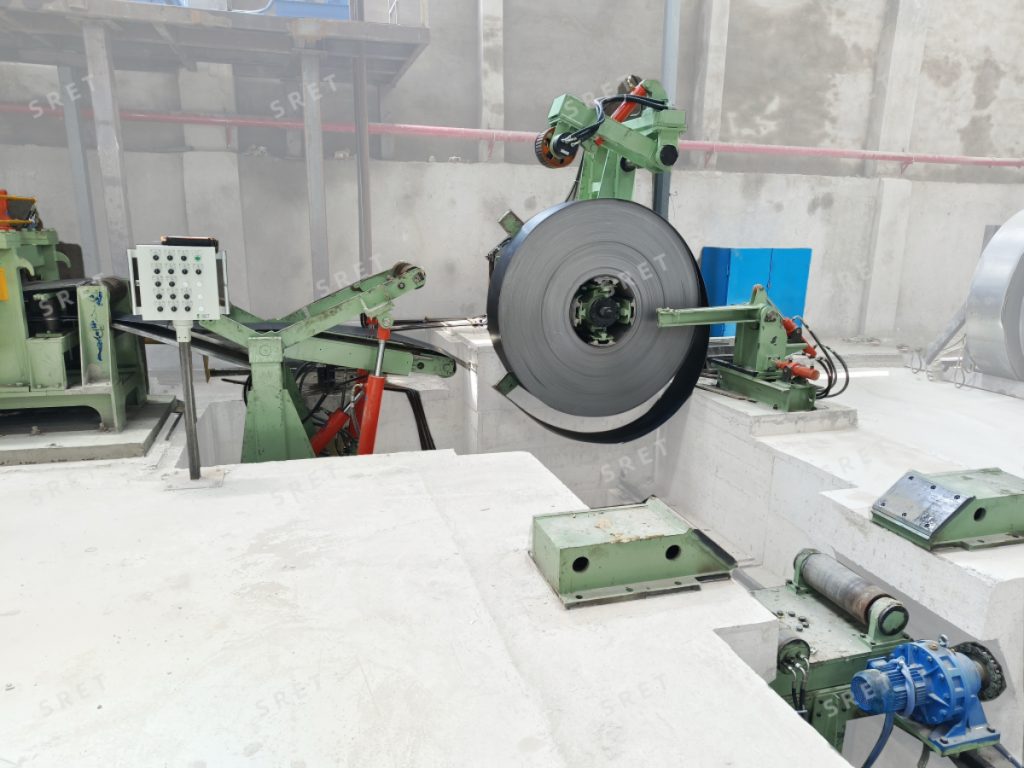
A loading sequence should have a clearly defined starting point.
Does the crane place the coil on a preparation saddle? Is a loading trolley included? Which equipment transfers the coil onto the drum or between the supporting heads?
The answers determine the responsibilities of the equipment supplier and the plant. A description such as “automatic loading” is incomplete unless the proposal identifies where automatic movement begins and which preparation tasks remain outside that sequence.
Before approving an ERW tube mill layout, confirm:
The layout should distinguish the coil-handling area from the strip path toward downstream equipment.
Coil weight alone is not enough to define the loading requirement. The project should also identify coil inside diameter, outside diameter, strip width and strip thickness.
SRET’s model data lists these dimensions separately. The proposed machine should be checked against the combinations expected in production, not only against individual maximum values.
For a tube mill machine proposal, provide both the normal production range and less frequent specifications. Ask the supplier to confirm the applicable combinations and any limitations affecting loading or unwinding.
If the future product range may change, document the intended requirement during selection rather than assuming that unused capacity in one dimension provides capacity in every other dimension.
Supporting a coil and presenting its strip head are different tasks.
The published arrangement describes a drum or supporting heads engaging the coil bore, followed by expansion or positioning to support the coil. A hold-down roll then acts on the outside of the coil, while the peeler head and coil-head straightener assist with preparing the leading end.
A technical review should identify the purpose of each supplied mechanism:
| Function | Point to Confirm |
| Coil support | How the coil is held in its operating position |
| Expansion or engagement | How the supporting mechanism fits the specified coil bore |
| Hold-down | How the outside of the coil is restrained during the relevant actions |
| Head opening | How the leading end is presented |
| Pre-straightening | Which device prepares the head for downstream transfer |
| Braking | How unwinding is controlled under the specified conditions |
This prevents a component name from being mistaken for a complete operating function.
The final operating procedure must follow the supplied machine instructions and site safety requirements. A general process description is not a substitute for an approved coil-handling procedure.
The interface with the flattener should be defined in the proposed layout and control sequence.
The review should establish the strip travel direction, working height and the point at which downstream equipment takes over feeding. It should also explain which devices guide or advance the strip during initial threading.
Useful questions include:
For an ERW tube mill machine project, these questions are more useful than a general promise of convenient operation. They establish what the supplied equipment is expected to do and where operator involvement remains necessary.
The product description states that the drum or supporting heads can be designed for active or passive rotation. The selected arrangement should be identified in the technical proposal.
The control review should distinguish between rotating the coil for head preparation and unwinding during normal strip feeding. It should also identify the braking arrangement and the signals exchanged with adjacent equipment.
Do not infer the unwinding design from the presence of a motor elsewhere on the machine. A powered hold-down roll, for example, does not by itself define how the drum operates throughout production.
Where forward and reverse rotation or different unwinding directions are required, confirm their availability and use for the proposed configuration.
Different uncoiler structures require different changeover arrangements.
The published range includes single-drum, double-drum rotatable and face-to-face drum or conehead designs. A statement that every machine allows one coil to be loaded while another unwinds should therefore not be applied across the range.
For the selected structure, the proposal should explain:
A double-drum description should not automatically be expanded into a claim of 180-degree indexing unless that movement is confirmed for the supplied machine.
When reviewing changeover time, define the tasks included in the quoted figure. Coil preparation, loading, threading and downstream joining may have separate timing boundaries.
The automation scope should be documented by function rather than by listing control components alone.
A tube mill line proposal should identify the available operating stations, permitted commands, status indications and interfaces with adjacent machines. If remote operation is included, clarify which actions are enabled and under what conditions.
The presence of a remote controller does not, by itself, establish safer operation. The supplied arrangement must address operator visibility, authorization and the applicable machine-safety requirements.
Similarly, where automatic loading functions are offered, confirm:
This makes the scope clearer than describing the entire machine as “fully automatic.”
Commissioning should verify the loading and threading functions included in the contract under agreed test conditions.
The acceptance plan should identify the coil specifications used, the expected sequence and the method for checking transfer to downstream equipment. It should also distinguish functional demonstration from claims about production improvement.
Record any conditions that require a different procedure, additional adjustment or operator intervention. These findings should be reflected in the operating documentation and training.
A well-defined uncoiler project connects coil delivery, support, head preparation, unwinding and downstream transfer into one documented arrangement.
This article addresses those interfaces rather than defining an individual machine’s capacity. For model-specific strip ranges, coil dimensions, weights and equipment structures, refer to SRET’s uncoiler specifications and configuration information.