A dual-mode flying cutoff combines single-blade sawing and double-blade orbital milling in one cutting system. Used in an ERW tube mill line, it cuts moving tubes to preset lengths while its travelling carriage follows the production speed.
The defining feature is not simply the presence of two blades. It is the ability to select between two cutting modes for different tube dimensions within the machine’s configured operating range. This article explains the two modes and how they fit into the flying cutting cycle.
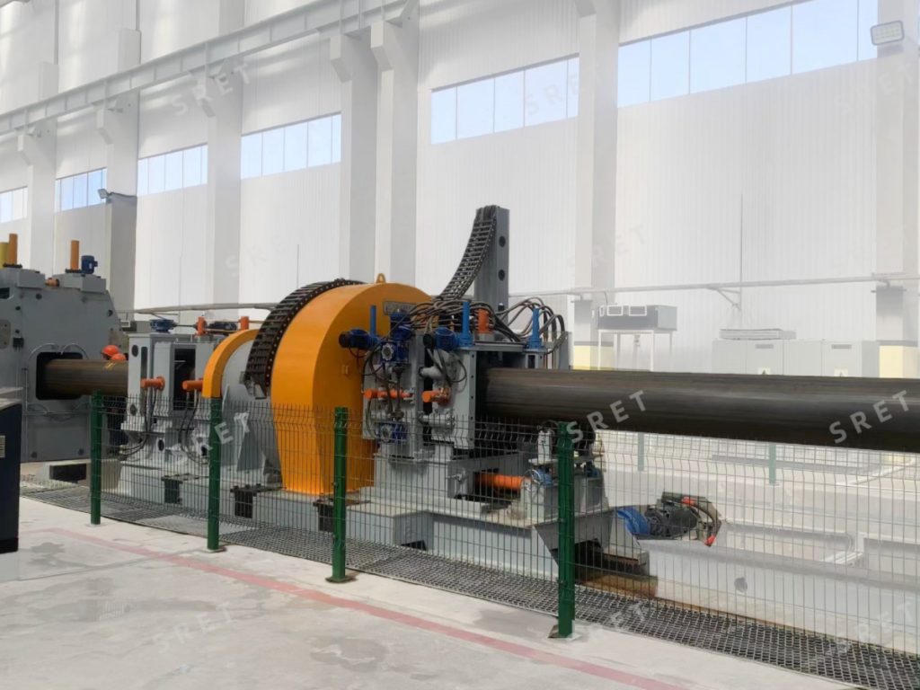
In the configuration described here, the cutting system provides two operating modes:
The control system selects the mode according to the tube-size settings and the machine’s programmed cutting configuration. The exact selection limits should be confirmed for the equipment rather than assumed from the number of blades.
Dual-mode operation does not mean that the machine changes modes arbitrarily during a cut. The selected mode forms part of the programmed cutting cycle for the tube specification being produced.
In single-blade mode, a spindle drive rotates the saw blade while a servo-controlled feeding mechanism advances it through the tube section. Ball screws and linear guides control the feeding movement.
The carriage remains synchronized with the moving tube during this operation. Blade rotation and blade feeding perform the cutting action, while carriage movement follows the tube along the production line.
This mode uses the single-blade sawing capability of the combined machine. Its applicable tube-size range and cutting settings are defined by the equipment configuration.
In double-blade milling mode, the two saw blades are mounted on sliding tables in a rectangular-coordinate profiling system. Their feeding paths combine horizontal X-axis and vertical Y-axis movements.
The controller coordinates these movements to produce the programmed cross-section profiling cut. Blade rotation provides the cutting action, while the X-Y feeding movements guide the blades along their assigned paths.
This description should not be confused with a sequential double-blade arrangement in which one blade completes an initial portion and another finishes the remaining cut. For orbital milling, the defining feature is the programmed profiling movement. The detailed coordination of the two blades depends on the machine design.
Both cutting modes use the same basic carriage-tracking sequence. The difference lies in the blade feeding operation carried out after synchronization and clamping.
Rectangular-coordinate feeding describes the blade movement within the cutting assembly. The horizontal and vertical axes combine to create a profiling trajectory suited to the programmed tube section.
These movements are separate from the carriage’s longitudinal travel. The carriage follows the tube along the line, while the X-Y axes guide the blades through the cross-section.
The system’s programming includes the feeding starting position, initial angle, profiling path and milling parameters. These settings define how the cutting units approach and process the selected tube section.
A specification change requires the cutting program and clamping arrangement to match the new tube dimensions. The availability of two cutting modes allows the configured system to use the appropriate programmed method for the selected size.
For the rectangular-coordinate configuration designed around a fixed tube bottom-line reference, the sawing system can accommodate size changes without a separate height adjustment of the sawing assembly.
This does not mean that no setup work is required. Cutting settings, clamp suitability and the permitted operating range still need to be checked. The no-height-adjustment feature should only be applied to the configuration for which it is specified.
The motion controller coordinates acceleration, synchronous tracking and return. S-curve control makes changes in carriage motion more gradual to reduce mechanical shock during starting and returning.
The HMI provides access to cutting settings, servo-position information, alarms and operating status. These functions help operators check the selected program and monitor the cutting cycle.
The clamping system holds the tube during cutting. Hydraulic or pneumatic actuation may be used according to the equipment configuration. Hydraulic stations and valve groups support the installed hydraulic functions where applicable.
A remote diagnostic module provides access to equipment-status information for troubleshooting. It supports fault assessment but does not replace on-site inspection or maintenance when these are required.
TCT and HSS blades are available according to the machine configuration. The selected tooling and cutting settings must suit the tube specification and operating mode.
Maximum line speed, cutting-length tolerance and wall-thickness limits should be checked for the selected model and configuration. A single speed or accuracy figure should not be applied to the entire product series.
The same applies to cut quality: the equipment is intended to produce clean cut surfaces, but the result depends on suitable tooling, blade condition, feeding settings and tube holding.
Single-blade sawing uses one blade with a controlled feeding movement. Double-blade orbital milling uses two blades following programmed profiling paths. The dual-mode machine combines these capabilities within one system.
The system selects the mode according to the configured tube-size settings and programmed cutting rules. The applicable size ranges and selection limits should be confirmed for the specific equipment.
No. In this description, X and Y refer to the blade feeding movements within the cutting assembly. The travelling carriage moves along the production direction to follow the tube.
Not for the specified rectangular-coordinate configuration using a fixed bottom-line reference. However, other setup checks and adjustments may still be required, and this feature should not be assumed for every orbital cutoff design.
Yes. After setup, the control system coordinates tracking, clamping, cutting and return automatically. Operators still need to monitor the equipment and follow the prescribed operating and maintenance procedures.
For available models, tube-size ranges, wall-thickness limits and cutting specifications, see the orbital milling type flying cutoff product page. Confirm the dual-mode configuration and its operating limits with the engineering team.