An uncoiler, also called a decoiler, supports a steel coil and releases the strip for the next stage of production. In an ERW tube mill line, it forms part of the entry section, supplying material toward the flattener or other downstream preparation equipment.
Its operation involves more than rotating a coil. Loading, coil support, strip-head opening, feeding and braking must work together. The required configuration depends on the coil dimensions, weight and handling arrangement.
This article explains the main operating stages and the information needed to specify an uncoiler for a welded tube production line.
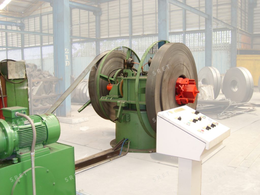
The uncoiler receives and supports the coil, holds it in the required position and allows the strip to unwind. In the equipment arrangement described here, a loading trolley transfers the coil from a preparation saddle to the uncoiler.
Associated devices can help restrain the outer wrap, open the coil head and guide it toward the next operation. The scope should distinguish the uncoiler itself from the loading trolley, peeler and coil-head straightening equipment supplied with it.
In the loading arrangement described in SRET’s product specification, the coil is first placed on a preparation saddle. A V-shaped loading trolley travels on guide rails and uses a hydraulic lift to raise the coil to the uncoiler’s supporting position.
The support mechanism then engages the coil bore. Depending on the selected structure, the equipment uses a drum or cone-head arrangement to support the coil. Where an expanding mandrel is used, it expands against the inside of the coil bore to secure the coil.
The loading arrangement should be checked against the permitted coil dimensions and weight. The presence of a loading trolley does not, by itself, define the capacity of the complete system.
The support structure carries the coil during unwinding. The selected drum, mandrel or cone-head arrangement must match the specified coil bore and loading conditions.
For an ERW Tube Mill, coil inner diameter, outer diameter, width and weight should be reviewed together. A suitable bore range alone does not establish that the equipment can handle the complete coil specification.
The hold-down roll contacts the outer portion of the coil to help restrain it during the coil-opening sequence. In the described arrangement, it also rotates to assist with opening the coil head.
This function should be distinguished from the mandrel’s role in supporting and securing the coil through its inner bore.
The peeler head works with the hold-down roll to open and direct the leading end of the strip. The coil head is then prepared by the specified straightening equipment before moving toward the flattener or the next process.
The technical proposal should identify which devices are included and how the strip head is transferred between them.
The uncoiler can be configured for active or passive rotation. Do not assume that every model uses the same drive arrangement.
The supplied product description also includes hydraulic or pneumatic braking arrangements to help control coil rotation and limit unwanted loosening. The brake type and operating sequence should be confirmed for the proposed equipment.
The following sequence summarizes the arrangement described in the supplied product information. Individual machines may use different controls or structures.
Operator responsibilities, automatic movements and the conditions for starting each step should be defined in the equipment documentation.
Active and passive rotation are alternative configurations identified in SRET’s product description. The appropriate arrangement should be reviewed as part of the complete entry-section design.
When comparing a tube mill machine proposal, ask the supplier to explain the uncoiler’s drive, feeding and braking functions. An adjustable unwinding drive should not automatically be described as a complete tension-control system unless that function is specifically included.
Also confirm the permitted unwinding direction. The described equipment includes forward and reverse rotation arrangements for the specified upper- or lower-unwinding configuration.
Selection should begin with the incoming coil specification and the planned loading process, rather than the nominal finished-tube size alone.
Provide the minimum and maximum strip widths and thicknesses. Ask the supplier to confirm the supported combinations for the intended materials.
The coil bore must match the operating range of the selected support and expansion arrangement. If coils arrive with different inner diameters, list each required range.
Specify both maximum outer diameter and maximum coil weight. Confirm that the uncoiler, loading trolley and associated handling equipment are selected for the agreed loading conditions.
The supplied model range includes single-drum, double-drum and rotatable double-drum structures. Availability varies by model, so these arrangements should not be treated as interchangeable options for every capacity.
Confirm the coil-loading route, strip travel direction, working height and connection to the next machine. For an existing-line upgrade, identify any limitations imposed by the current factory layout and entry equipment.
The supplied product description includes configurations with automated loading calculations, coil centering and advance deceleration or braking near the coil tail.
For an ERW tube mill machine proposal, ask which of these functions are included, what coil information the operator must enter and which tasks still require manual action.
Similarly, confirm where variable-frequency drives are used. The loading trolley and unwinding drive may have separate requirements, and their functions should be described individually.
These devices form related parts of the entry process, but they should not be described as performing the same task.
The supply scope should show how these functions are divided between machines and how the strip is transferred from one operation to the next.
Both terms are used in the supplied product information for equipment that supports the coil and releases the strip. The technical specification should still define the actual structure and included functions.
No. The supplied equipment description allows active or passive rotation. Confirm the arrangement for the proposed model.
Its primary function is coil support and unwinding. Associated coil-head preparation equipment and the downstream flattener perform separate preparation tasks.
Do not assume that it is. The proposal should identify the included loading equipment, control functions and operator responsibilities.
Provide the material specification, strip-width and thickness ranges, coil inner and outer diameters, maximum coil weight and intended loading arrangement. Include the layout and downstream equipment requirements for the proposed ERW tube mill line.