A single drum uncoiler supports one coil in its operating position and releases the strip toward the next entry-section machine. Before regular feeding begins, the coil must be loaded, secured and opened so that its leading end can be guided into the downstream equipment.
In an ERW tube mill line, these stages involve different mechanisms. The loading trolley positions the coil, the drum supports it, and the coil-opening equipment prepares the leading end for threading.
This article explains those functions using the proposed configuration described here. The exact sequence and supplied devices must follow the documentation for the selected machine.
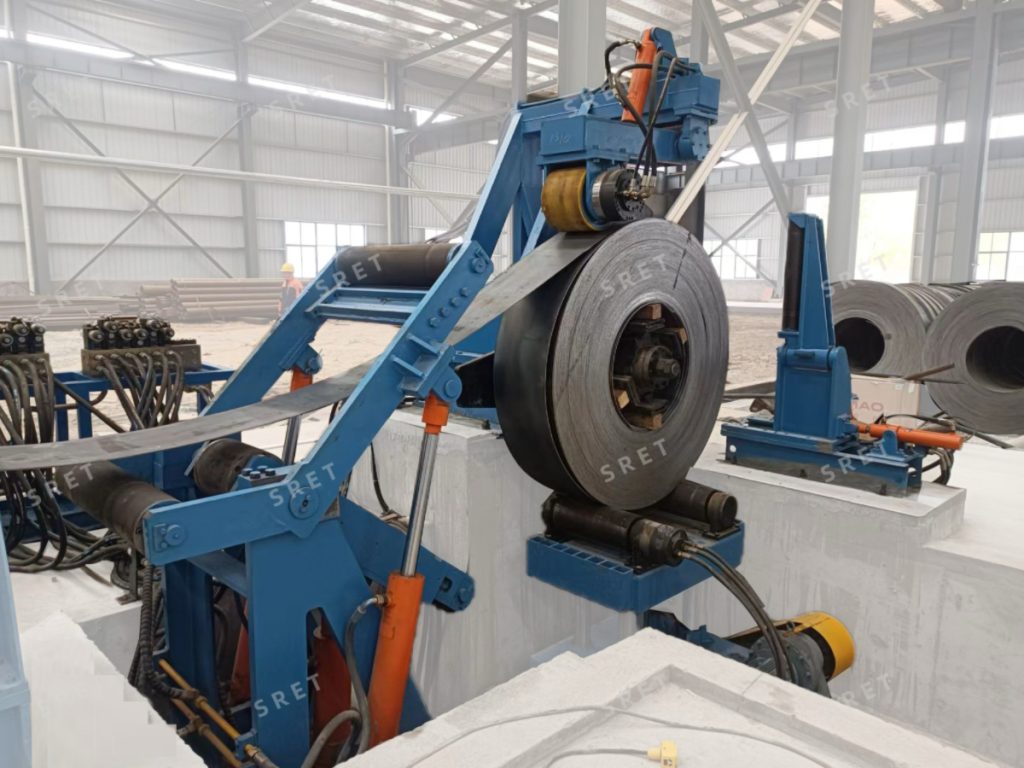
Loading transfers the coil onto the uncoiler support. Unwinding releases strip from the secured coil. The equipment and controls used for these actions should be identified separately.
In the described arrangement, the coil is first presented on a preparation saddle. A rail-mounted, V-shaped loading trolley then positions and raises it to the required loading height.
The trolley drive, hydraulic lift and uncoiler support must be selected for the agreed coil dimensions and weight. A trolley specification alone does not establish the capacity of the complete loading arrangement.
The expanding drum engages the coil bore and secures the coil through the specified expansion mechanism.
Associated devices act on other parts of the coil. The hold-down roll contacts the outer wrap, while the block-roll device performs the restraint function defined in the equipment design.
These devices should not be treated as interchangeable. Supporting the coil through its bore, restraining the outer wrap and controlling rotation are different tasks.
The operating documentation should define how support is transferred from the loading equipment and what conditions are required before coil opening begins.
In the proposed arrangement, the hold-down roll works with the peeler to open and guide the leading end. The coil head then passes through the specified coil-head straightening equipment.
This preparation should be distinguished from the downstream flattener’s function. The coil-opening devices establish and guide the leading end, while the flattener prepares coil ends for subsequent processing.
The proposal should identify the permitted movements, operator actions and transfer path between these devices.
Once the leading end has been prepared, it is guided toward the receiving equipment. In the described arrangement, the flattener’s inlet pinching rolls assist with advancing the strip into the next section.
For a tube mill line, the threading interface should define:
These details should be confirmed for the installation rather than assumed from a general equipment description.
The supplied information allows active or passive drum rotation. The specific arrangement must be stated in the technical proposal.
A passive drum should not be described as lacking rotational control altogether. The proposed equipment may still include a brake and separately powered coil-opening devices.
Likewise, a powered hold-down roll does not by itself establish that the drum has an active unwinding drive. Each drive function should be listed separately.
The required unwinding arrangement depends on the specified strip path. Confirm the permitted direction of drum rotation together with the locations of the peeler, guides and receiving equipment.
The supplied draft describes a lower-unwinding arrangement using powered support rolls on the loading trolley. If this option is selected, the equipment drawing and operating procedure should explain when those rolls engage and what support they provide.
Do not assume that the loading trolley remains in contact with the coil during every machine’s normal unwinding cycle.
The proposed configuration includes a braking device to control coil rotation and limit unwanted loosening. Its actuation method and operating sequence should be specified for the selected equipment.
When reviewing a tube mill machine proposal, distinguish between:
Control hardware such as an HMI, PLC, VFD or remote-control receiver should be linked to its actual function. A component list alone does not define the level of automation.
For an ERW tube mill machine, provide the strip-width and thickness ranges, material specifications, coil inner diameter, maximum outer diameter and maximum weight.
Also confirm:
Additional support should be assessed for the specified machine and loading conditions. A single coil-weight threshold should not replace that review.
No. The supplied description allows active or passive rotation. Confirm the arrangement for the selected machine.
The quotation should state whether the preparation saddle, trolley and associated support devices are included. Do not assume the same scope for every configuration.
Their roles should be identified separately. Coil-head preparation assists with opening and threading, while the downstream flattener performs its specified strip-end preparation task.
The requirement should follow the selected support structure and loading conditions, not a universal threshold applied to every machine.
For listed coil dimensions, weight capacities and equipment structures, see SRET’s uncoiler product page. Project-specific loading and threading arrangements should be confirmed in the technical proposal.