Connecting the tail of one steel coil to the head of the next requires more than completing a weld. The strip ends must first be positioned, trimmed and brought into the required joint arrangement. They must then remain securely located while welding takes place.
A shear end welder coordinates these operations within the entry section of an ERW tube mill line. This article focuses on the relationship between shearing, alignment, clamping and welding, using the operating sequence described for SRET’s equipment.
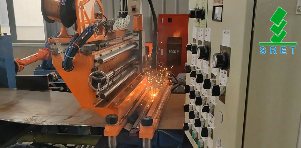
Although the operations are integrated, they perform different functions:
These functions should be understood separately. Centering the strip does not complete joint preparation, and positioning the welding gun does not replace mechanical alignment or clamping.
As the outgoing coil approaches its end, the remaining tail is retained at the exit side of the shear end welder.
In the described arrangement, the rear center-aligning mechanism locates the strip relative to the machine centerline. Rear pinching rolls then make the longitudinal adjustment needed to place the intended trimming location at the shear blade.
This distinction matters: the aligning mechanism addresses strip position across the machine, while the pinching rolls advance or position the strip along its travel direction.
The shearing platens clamp the strip before the hydraulically actuated blade removes the irregular tail section.
The next coil head arrives from the uncoiler and flattener. The front center-aligning mechanism positions it relative to the previously located tail.
The incoming head is advanced to the shearing position and clamped before trimming. In the published operating sequence, an overlap is used during this preparation stage.
That temporary overlap should not be confused with the final joint type. The equipment subsequently establishes the trimmed ends in a butt-joint arrangement for welding.
After trimming, the shearing device withdraws and the welding base plate rises. The equipment then establishes the specified separation between the coil tail and head.
At this stage, three different conditions should be distinguished:
The required joint gap should follow the approved setup for the material, thickness and welding process. It should not be presented as one universal value for every model or application.
The welding unit moves into position, and the left and right compression platens hold the prepared strip ends.
These welding clamps perform a different task from the platens used during shearing. The earlier clamping action holds the material for cutting; the welding-stage clamping retains the prepared ends during joining.
The welding gun is then positioned relative to the seam before automatic welding begins. Gun positioning and strip alignment are related, but they are not interchangeable operations.
When reviewing the equipment sequence, confirm which mechanism establishes each position and which settings or operator actions are required.
Once the prepared ends are clamped and the welding unit is positioned, the automatic welding operation starts. After completion, the equipment resets for the next joining cycle.
The joined strip is then fed toward the accumulator. The shear end welder creates the connection between successive coils, while the accumulator provides the strip reserve used during the interruption in entry feeding.
These machines therefore perform complementary functions. Completing a joint does not, by itself, establish that the downstream mill can operate without interruption; the joining sequence must also fit the available operating window.
The welding method should be confirmed for the selected equipment rather than assumed from the term “automatic shear end welder.”
SRET’s published model table lists TIG, TIG/MIG and MIG configurations across the range. A single process description should therefore not be applied to every model.
Likewise, details such as welding-gun quantity, travel drive, backing-plate material and shielding-gas specification should be stated in the project’s technical documentation.
A useful process review follows the sequence of operations instead of checking only whether the welding gun can traverse the strip.
| Stage | Item to Confirm |
|---|---|
| Tail positioning | How the outgoing strip is centered and located at the shear. |
| Head preparation | How the incoming strip is aligned, advanced and trimmed. |
| Joint setup | How the trimmed ends and specified joint gap are established. |
| Welding restraint | Which clamps hold the ends during welding. |
| Welding operation | The applicable process, settings and gun-positioning arrangement. |
| Completion | The reset sequence and conditions for resuming strip transfer. |
Acceptance requirements should identify how the completed joint will be checked and which operating conditions apply. Automatic movement alone should not be treated as proof that the joint meets every production requirement.
Welding travel time is only one part of a coil-joining operation. Positioning, trimming, joint preparation, clamping and reset also occupy time.
When assessing the entry section of a tube mill line, confirm what the quoted cycle time includes. If additional operator tasks or checks fall outside that figure, identify them separately.
This provides a clearer basis for reviewing the joining operation alongside the accumulator’s usable reserve and the intended mill speed.
Not by itself. Center alignment positions the strip relative to the machine reference. The trimmed ends must also be placed in the required relationship for welding.
No. In the operating sequence described here, overlap occurs during end preparation. The equipment subsequently establishes a butt-joint arrangement.
They restrain the strip at different stages. Shearing platens hold the material during cutting, while the welding-stage platens hold the prepared ends during joining.
No. The applicable process depends on the equipment configuration. Confirm it in the model data and project specification.
No. The joining operation must be coordinated with the entry section and the available accumulator reserve. The operating conditions of the complete line must be reviewed.
This article explains the joining sequence rather than defining the capacity of an individual machine. For strip-width and thickness ranges, listed cycle times and model-specific welding options, see SRET’s shear end welder product page.