Changing tube size on a dual-mode flying cutoff involves more than selecting a new cutting length. The cutting mode, blade feeding path, clamping arrangement and operating limits must match the new tube specification.
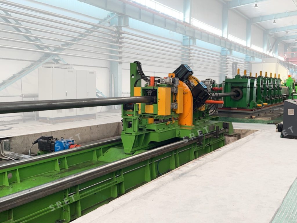
In an ERW tube mill line, the dual-mode configuration described here combines single-blade sawing with double-blade orbital milling. Its rectangular-coordinate feeding system provides programmed X-Y blade movements, while the travelling carriage follows the moving tube during cutting.
This article focuses on specification changeover: what the fixed bottom-line arrangement can simplify, and which checks remain necessary before production resumes.
A different tube section changes the relationship between the workpiece, clamps and cutting tools. The new specification may require a different cutting mode, feeding trajectory or tooling setup within the machine’s permitted range.
Before selecting a cutting program, the relevant production data should be confirmed:
For an ERW Tube Mill, these settings must correspond to the tube specification leaving the sizing section. A stored program should not be treated as suitable simply because its nominal tube size appears similar.
Single-blade mode uses one saw unit with a controlled feeding movement to complete the cut. The spindle rotates the blade, while the feeding mechanism guides it through its programmed path.
The permitted tube range and feeding settings depend on the specific equipment configuration.
Double-blade milling mode uses two saw units following programmed profiling paths. In the rectangular-coordinate arrangement, horizontal X-axis and vertical Y-axis movements combine to guide the blades through the tube section.
This should not be confused with a sequential double-blade cutoff solely because both machines use two blades. The defining feature here is the profiling movement.
The dual-mode system can select the cutting mode according to the configured tube-size settings and programmed selection rules. Those rules must be confirmed for the machine; the controller should not be described as independently determining an unrestricted “optimal” mode for every tube.
A fixed bottom-line arrangement uses the bottom of the tube as the common reference across the specified product range. This differs from assuming that every tube size is positioned around an unchanged center height.
For the rectangular-coordinate configuration described in the equipment documentation, the sawing assembly does not require a separate height adjustment when changing tube size within the applicable range.
This feature simplifies one part of changeover. It does not mean that every component remains unchanged or that the machine requires no setup checks.
The installed jaws must suit the new tube profile and dimensions. A fixed bottom-line reference does not establish that one complete jaw set is suitable for every specification.
Any shared-jaw arrangement or reduction in the number of required jaw sets should be confirmed against the actual product range and fixture design.
The feeding starting position, approach angle, profiling trajectory and cutting parameters must correspond to the selected tube section and operating mode.
The purpose of the programmed path is to coordinate cutting and withdrawal within the machine geometry. It should not be assumed that the same trajectory applies to every tube size.
TCT or HSS blades may be supplied according to the configuration. The installed tooling must be suitable for the intended material, tube dimensions and cutting mode.
Blade selection should follow the equipment’s tooling requirements rather than a general statement that either blade type is interchangeable for all applications.
Maximum line speed, cutting-length range and stated length tolerance must be checked for the selected model and configuration.
For a tube mill machine, these limits form part of the production setup. A general maximum speed for the entire product family should not replace the specification for the actual cutting application.
Both modes use the flying carriage to follow the moving tube. Measurement signals are supplied to the control system, the carriage accelerates to the tracking speed, and the fixtures hold the tube during cutting.
After the selected cutting operation is complete, the blades withdraw, the clamps release and the carriage returns for the next cycle.
The distinction is between two coordinated functions: carriage motion follows the tube along the line, while blade feeding performs the selected cutting path through its cross-section.
The HMI provides access to the configured cutting settings, servo-position information, alarms and operating status. It supports checking the selected program before the next production run.
A typical changeover review should follow the machine’s operating procedure and confirm:
For an ERW tube mill machine installation, the cutoff setup must also be coordinated with the downstream tube-handling arrangement.
A remote diagnostic module provides access to available equipment-status information for troubleshooting. It can assist with assessing alarms and control-system conditions.
It does not replace physical checks of blade condition, jaw installation, tube support or mechanical clearance. Remote access should therefore be treated as a support function, not as a guarantee of fault-free or unsupervised operation.
Not for the specified rectangular-coordinate configuration designed around a fixed bottom-line reference. This feature must be confirmed for the machine and its permitted product range.
No. Cutting programs, mode selection, tooling, clamping fixtures and operating limits still need to be checked.
It uses the configured tube-size settings and programmed selection rules. The applicable limits and selection logic should be confirmed for the equipment.
That depends on the fixture design and product range. Any shared-jaw capability must be verified rather than inferred from the fixed bottom-line arrangement.
No. The permitted speed must be checked for the selected model, tube specification and cutting configuration.
No. Automatic sequencing performs the programmed cycle, but operators still need to complete setup checks, monitor alarms and follow the machine’s operating procedures.
For available models, tube ranges, cutting specifications and dual-mode configuration details, see the orbital milling type flying cutoff product page.