The performance of a coil-end joining sequence depends on several mechanisms working together. Strip positioning, trimming, clamping and welding are separate tasks, even when they are coordinated within one automatic machine.
A shear end welder brings these functions together in the entry section of an ERW tube mill line. This article explains the responsibilities of its main assemblies and the hydraulic and electrical interfaces that should be defined in a technical proposal.
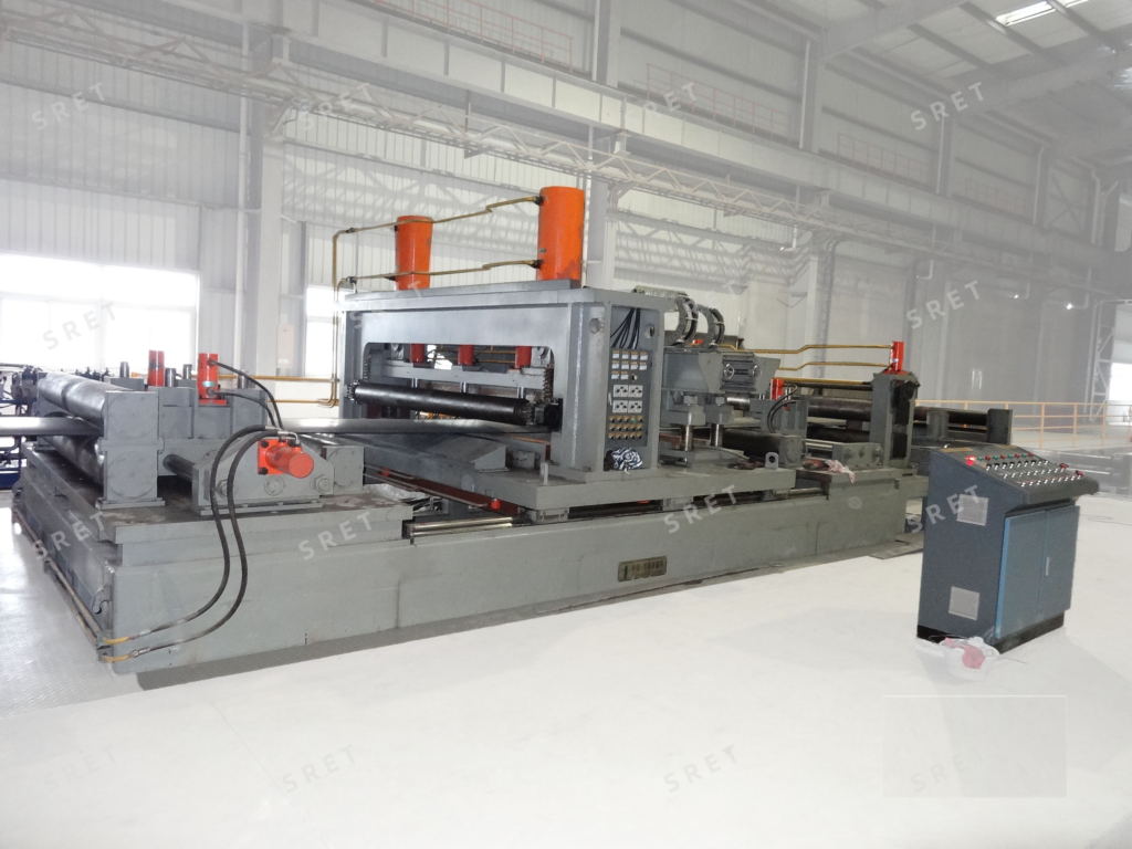
A useful equipment review separates the machine into three groups:
The presence of these groups does not establish that every machine has the same configuration. The supply scope should identify the components and functions included for the selected model.
The machine bed carries the installed assemblies. The equipment drawing should show the positions of the strip-handling, shearing and welding sections, together with the required installation interfaces.
For an existing-line project, confirm the working height and strip path rather than assuming that the new machine will match the surrounding equipment without adjustment.
The center-aligning mechanisms position the incoming coil head and outgoing coil tail relative to the machine reference.
In SRET’s published operating description, front and rear mechanisms act on the two strip ends at different stages. Their function should be distinguished from the longitudinal movement used to place the trimming location at the shear blade.
The pinching rolls feed or finely position the strip. In the described sequence, rear pinching rolls adjust the outgoing tail so that the section to be removed is located at the shear.
These rolls should not be described as the only devices holding the strip throughout cutting and welding. Dedicated platens provide restraint during those operations.
The shearing assembly includes the blade and the associated clamping arrangement. The platens hold the strip before the hydraulically actuated blade trims the irregular end section.
Both coil ends are prepared before the final butt-welding operation. This should not be confused with a process that necessarily trims the joint again after welding.
After end preparation, the shearing device withdraws and the welding base plate rises. The prepared ends are then positioned in the required relationship for welding.
The left and right welding compression platens hold the ends while the welding operation takes place. Their role differs from that of the shearing platens, which restrain the strip during cutting.
The welding unit moves into position and the gun or torch is aligned with the joint. The supplied equipment specification should identify the welding process, travel arrangement and adjustment functions.
Associated components depend on the selected process. A wire-feeding mechanism, welding power source and torch arrangement should be listed according to the actual configuration rather than copied into every model description.
SRET’s published model table includes TIG, TIG/MIG and MIG entries, so one universal welding package should not be assumed across the complete range.
The published machine sequence includes hydraulic actuation of the shear blade. Other hydraulic functions should be identified in the project documentation.
If the proposed machine shares a hydraulic station with other entry-section equipment, the specification should state that arrangement explicitly. It should also identify the functions served and the interfaces between the shared station and the machine.
A shared supply should not automatically be described as providing a particular space or cost saving. Those benefits depend on the actual equipment scope and installation layout.
The electrical description should explain how the machine operates, not simply list control hardware.
For the specified configuration, clarify:
If the machine shares the entry section’s electrical control system, identify the control boundary and the purpose of any local operating box.
The presence of a local control box should not be treated as proof that remote diagnostics or automatic troubleshooting are included.
The complete joining operation depends on coordinated actions rather than one mechanism performing every task.
| Task | Main Assembly or Function |
|---|---|
| Position the strip across the machine | Center-aligning mechanisms |
| Advance or finely position the strip | Pinching rolls |
| Restrain the strip for trimming | Shearing compression platens |
| Remove irregular end sections | Shear blade and actuation system |
| Prepare the joint position | End-positioning and welding base-plate arrangement |
| Hold the prepared ends during welding | Welding compression platens |
| Complete the joint | Specified welding unit and travel mechanism |
This division helps avoid vague descriptions such as “the feeding rolls align and clamp everything automatically.” Each stage should be traceable to the mechanism responsible for it.
After joining, the connected strip is fed toward the accumulator. The shear end welder creates the connection between successive coils; the accumulator provides the strip reserve used during the interruption in entry feeding.
Fast joining and available storage must therefore be reviewed together. A shear end welder alone should not be described as guaranteeing uninterrupted operation of the complete tube mill line.
Similarly, welding travel time is only part of the total joining sequence. Positioning, trimming, joint preparation, clamping and reset must also be considered when reviewing cycle-time requirements.
Before approving the configuration, confirm:
For model-specific strip dimensions, listed cycle times and welding options, see SRET’s shear end welder product page.
No. The pinching rolls feed or position the strip, while the welding compression platens hold the prepared ends during joining.
This should be confirmed for the proposed configuration. Shared systems should not be assumed from the machine name alone.
No universal component list should be assumed. The welding package must match the specified process and model.
No. The complete joining sequence must be coordinated with the entry equipment, available accumulator reserve and intended operating conditions.