A double drum rotatable uncoiler provides two coil-support positions that can be brought into the required operating position through a rotating arrangement. Its purpose is not simply to add a second drum, but to organize coil preparation and changeover around the entry-section workflow.
For an ERW tube mill line, this arrangement should be evaluated alongside loading, coil-head preparation, strip joining and accumulator operation. Preparing a standby coil can reduce work left to complete at changeover, but it does not eliminate every interruption in entry feeding.
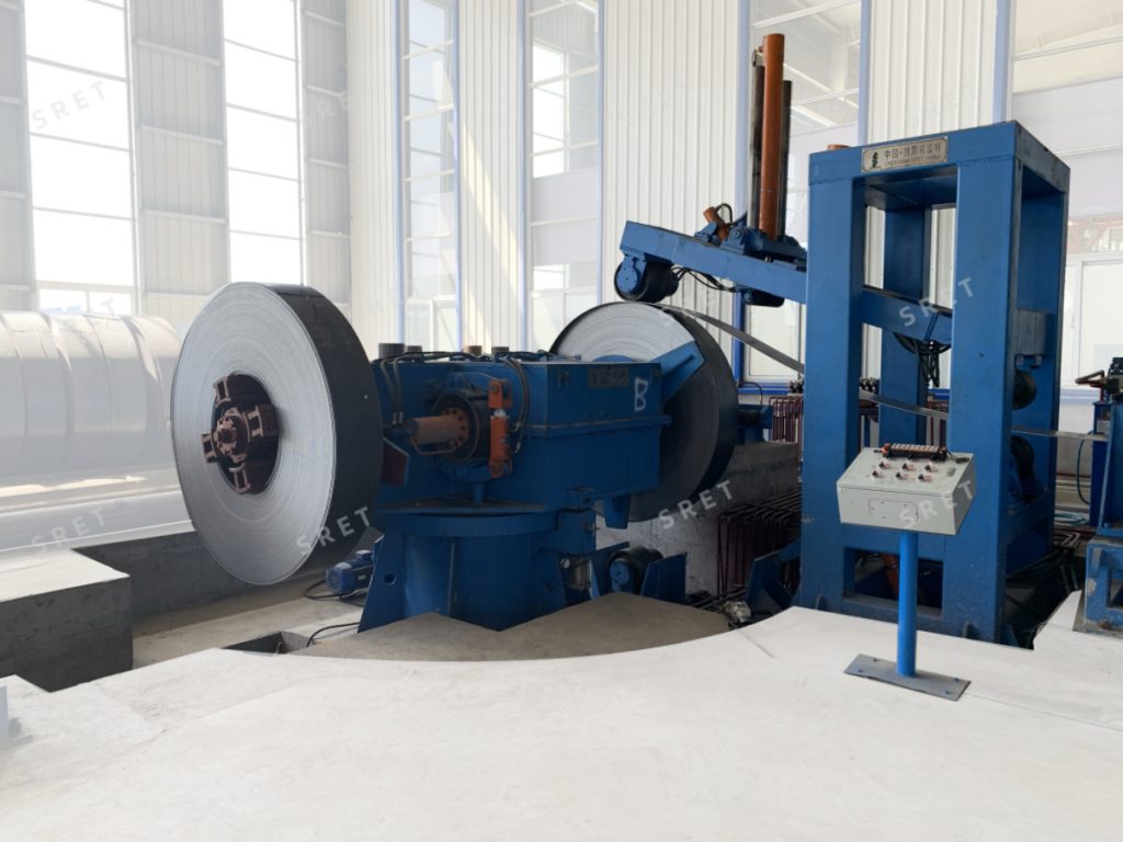
The word “rotatable” can describe a different movement from normal coil unwinding. These movements should be distinguished when reviewing the equipment.
The drive, movement limits and operating conditions for each action should be identified separately. A statement that the drum supports active or passive unwinding does not explain how the changeover mechanism operates.
In the alternating arrangement described for this application, one drum supports the coil being unwound while the other position is used to prepare the next coil.
The practical benefit comes from completing permitted preparation tasks before the active coil is exhausted. These may include presenting the next coil, loading it and securing it according to the specified equipment sequence.
The proposal should define which tasks can take place while the active side is operating. A standby position should not be interpreted as permission for unrestricted personnel access during machine movement.
A prepared coil still has to be brought into the operating position. Its leading end must then be opened and guided toward the next entry-section process.
Where successive coils are joined, the new head must also pass through the required preparation and connection sequence. The uncoiler therefore contributes to changeover preparation, while other entry equipment performs separate tasks.
This distinction matters when assessing a tube mill line. A reduction in loading-related waiting time should not automatically be described as an equal reduction in the complete coil-to-coil joining cycle.
The exact sequence depends on the supplied machine. The following stages provide a framework for reviewing the proposed arrangement rather than a universal operating instruction.
The loading arrangement places the coil onto the designated support. Where a preparation saddle and loading trolley are supplied, their movements and lifting capacity should match the proposed coil range.
Confirm whether this equipment is included in the quotation or supplied separately.
The specified expansion mechanism engages the coil bore. Associated restraint devices are positioned according to the machine’s operating procedure.
Coil support, bore engagement and outer-wrap restraint perform different functions. The technical documentation should identify each mechanism rather than describe them collectively as “automatic locking.”
Before the drum arrangement changes position, the active coil must reach the required condition for changeover. The procedure should define the status of the remaining strip, downstream equipment and any devices that must be clear.
The changeover movement should not be assumed to occur automatically whenever a coil is nearly empty.
The rotating arrangement brings the next drum to the required position. The rotation angle, direction and permitted movements should be confirmed in the equipment drawing and control description.
The hold-down roll and the specified coil-opening devices assist with preparing the leading end. Where a peeler and coil-head straightener are included, their roles should be shown in the sequence.
The prepared strip head then moves toward the flattener or the next process station.
The supplied product description allows active or passive rotation of the coil-support arrangement. This choice should be reviewed separately from the rotating changeover structure.
When assessing a tube mill machine proposal, confirm:
The presence of a driven hold-down roll should not, by itself, be used to describe the complete unwinding arrangement as actively driven.
Two available drum positions do not define the machine’s coil capacity. The incoming coil specification remains the starting point for selection.
Provide the strip-width and thickness ranges, coil inner diameter, maximum outer diameter and maximum coil weight. Confirm the supported combinations for the proposed equipment.
SRET’s supplied model table identifies KJ32 through KJ114 as double drum rotatable structures. Other entries use different structure descriptions, so the same changeover arrangement should not be assumed across the complete model range.
For an ERW tube mill machine, also review loading access, available space, strip travel direction and the working height of the next entry machine.
Names such as HMI, PLC and VFD identify control components, but they do not fully describe the automatic sequence.
A useful proposal should state which loading, securing, opening and changeover actions are automatic. It should also identify the required operator inputs and the conditions that permit each movement.
If remote control is supplied, clarify which movements it operates. A remote-control receiver should not be treated as evidence that remote diagnostics or remote maintenance are also included.
The uncoiler supports and releases the coil. The flattener prepares the strip ends, the shear end welder joins successive coils, and the accumulator provides the available strip reserve during the specified interruption in entry feeding.
These functions should be reviewed together when assessing changeover performance. Standby-coil preparation is one part of the workflow, not a substitute for the joining process or storage capacity.
No. It supports the planned loading and preparation arrangement. Continued downstream production also depends on the complete entry sequence and available strip reserve.
No. Changeover rotation repositions the drum arrangement. Unwinding rotation releases strip from the coil.
Do not assume that it does. Confirm the arrangement through the model specification, drawing and operating sequence.
The permitted sequence must be confirmed for the supplied equipment. The machine layout and operating procedure should identify which tasks can take place and under what conditions.
The quotation should define the included loading equipment and control functions. They should not be assumed from the product name alone.
For coil dimensions, weight capacities and listed equipment structures, see SRET’s uncoiler product page. The rotating arrangement and project-specific operating sequence should be confirmed in the technical proposal.