A face-to-face uncoiler uses opposing support members to hold a steel coil during unwinding. Depending on the equipment design, the support arrangement may use drums or cone heads.
Within an ERW tube mill line, the uncoiler receives the coil from the loading equipment, supports it in the operating position and releases the strip toward the flattener or the next entry-section process.
This article explains the proposed equipment arrangement, loading sequence and technical details that should be confirmed before selecting a drum or cone-head configuration.
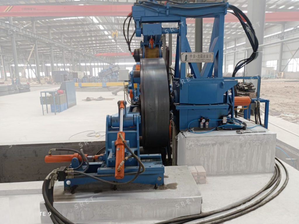
In the arrangement described here, two opposing support members engage the coil from opposite sides. The technical drawing should show their positions, travel and method of supporting the coil.
This arrangement should not be confused with a rotating two-position uncoiler. A description such as “double drum” is not enough on its own to establish whether the machine uses opposing supports or separate loading and unwinding positions.
For an ERW Tube Mill project, confirm the actual structure through the equipment layout and operating sequence rather than relying only on the model name.
The proposed equipment may use a drum arrangement or a pair of opposing cone heads. Their engagement and securing methods should be identified separately in the technical specification.
Where an expanding drum is supplied, the proposal should define its expansion range and method of securing the coil bore. For a cone-head arrangement, it should explain how the heads engage, support and retain the coil.
Do not assume that both structures use the same expansion-and-contraction mechanism simply because they perform the same general coil-support function.
The configuration described in the supplied project information includes the following equipment groups. The quotation should distinguish included items from optional or separately supplied equipment.
The loading trolley positions and raises the coil to the required loading height. Its capacity and travel should be checked against the proposed coil range and factory layout.
The proposal should define the permitted coil inner diameter, outer diameter, width and weight for the complete support arrangement.
These devices support the opening and preparation sequence. Their functions, movement limits and operator responsibilities should be explained in the supplied documentation.
The sequence below summarizes the arrangement described in the supplied information. The exact sequence depends on the selected support structure and controls.
The transfer of coil support from the loading trolley to the uncoiler should be defined in the operating procedure. Loading, securing and opening should not be treated as one unspecified automatic action.
The supplied description allows the drums or cone heads to be configured for active or passive rotation. The appropriate arrangement should be confirmed for the complete entry-section design.
When reviewing a tube mill machine proposal, identify which components are driven, how unwinding is controlled and how braking is coordinated with the strip-feeding sequence.
A powered loading trolley does not, by itself, mean that the uncoiler also has an active unwinding drive. These functions should be listed separately.
The described hydraulic equipment includes a hydraulic station and valve groups. The technical specification should identify which movements and pressure functions they control.
The proposed electrical package lists an operator console, local control stations, an electrical control cabinet, HMI, PLC, variable-frequency drives and a remote-control receiver.
These component names do not establish the level of automation on their own. For an ERW tube mill machine, ask the supplier to explain:
A remote-control receiver should not be described as a remote diagnostic or maintenance system unless those functions are separately included.
Selection should be based on the actual coil requirements. A statement such as “recommended above 4 mm thickness” is not a substitute for confirming the complete operating range.
For a Tube Mill Line inquiry, provide:
If coil inner diameters vary, list the required range and ask how the proposed support arrangement accommodates it. The supplier should confirm the engagement range and any adjustments or change parts required.
For an overview of SRET’s equipment range, see the uncoiler product page. Project-specific support structures and operating limits should be confirmed in the technical proposal.
Not necessarily. In the arrangement discussed here, opposing supports engage one coil. The equipment drawing should clarify the structure rather than relying on the term “double drum.”
Do not assume that it does. The support, engagement and securing methods should be defined for the proposed design.
A thickness threshold alone is insufficient. Coil dimensions, weight, inner-diameter range and the proposed support arrangement must also be reviewed.
Both arrangements are identified in the supplied description. Confirm the proposed drive and braking configuration for the application.
No. The supplier should define the actual automatic sequence, required operator inputs and manual tasks.
Review the coil-loading route, support alignment, working height, available space, strip path and interfaces with the next entry-section machine.