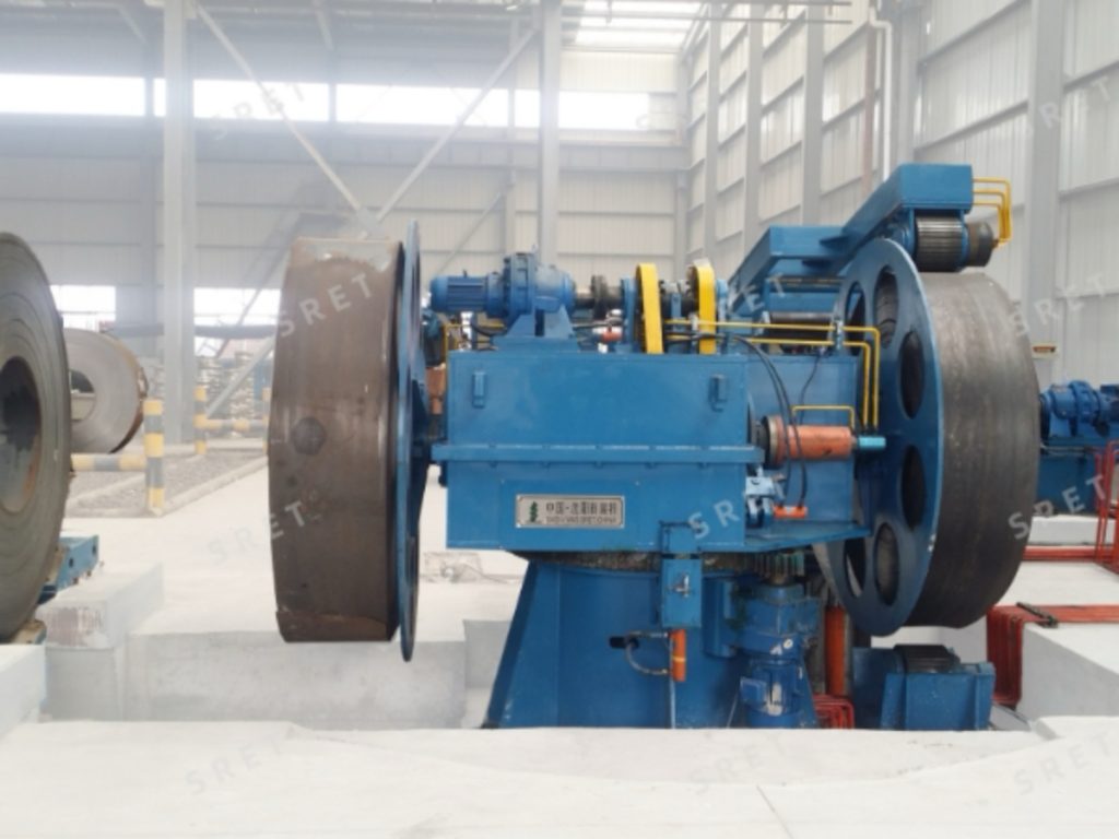
An uncoiler supports a steel coil and releases the strip toward the next entry-section operation. For an ERW tube mill line, the selected configuration must match the coil dimensions, weight, loading arrangement and downstream equipment.
Uncoilers are often described using terms such as single drum, double drum, rotatable double drum or cone-head support. These terms should be reviewed carefully because the coil-support structure, loading arrangement and drive system describe different aspects of the machine.
This guide explains how to compare uncoiler configurations without assuming that one structure is automatically suitable for a particular production scale or quality level.
A useful technical proposal should identify more than a model name. It should explain:
Keeping these items separate makes it easier to compare proposals for a Tube Mill Line and avoids treating every feature as a standard part of one equipment category.
SRET’s supplied model table identifies rotatable double-drum structures for several models. When reviewing this arrangement, ask how the drum positions are used during loading, unwinding and changeover.
The proposal should define the rotation mechanism, operating sequence and conditions for changing positions. A specific rotation angle or simultaneous loading sequence should not be assumed from the term “rotatable double drum” alone.
Any claimed reduction in coil-change time should also be assessed against the complete loading and entry-section process.
A single-drum uncoiler should be selected according to its specified coil capacity and operating arrangement. The term does not, by itself, mean that the equipment is limited to small coils or low production volumes.
For example, the supplied model table lists KJ273 as a single-drum structure with a maximum coil weight of 18 t. This illustrates why structure names should be considered alongside the actual technical data.
Review the loading method, available space, coil-opening equipment and downstream interfaces for the proposed model.
The supplied product description refers to drum or cone-head support, while the model table also lists double-drum structures. The technical proposal should clarify the actual arrangement rather than relying on these labels alone.
If an opposed-support arrangement is proposed, request a drawing showing how the coil is loaded, supported and released. Confirm the permitted coil inner diameters, widths and weights for that specific design.
Do not use a general strip-thickness threshold as a substitute for this engineering review.
The original equipment description allows active or passive rotation. The drive arrangement should therefore be confirmed separately from the number or layout of drums.
When reviewing a tube mill machine proposal, ask how unwinding is controlled, where the drive is located and how braking is coordinated with the feeding sequence.
Similarly, forward and reverse rotation should be distinguished from the permitted upper- or lower-unwinding layout. The required strip path must be confirmed in the proposed equipment arrangement.
The supplied product description includes a preparation saddle, a rail-mounted loading trolley, hydraulic lifting, a hold-down roll and a peeler arrangement. These items support different stages of loading and coil-head preparation.
These functions should not be described as exclusive to one structural category unless the manufacturer has confirmed that limitation.
Provide the actual inner-diameter requirements for the coils to be processed. The supplied model table contains different inner-diameter ranges, so one nominal size should not be presented as suitable for every model.
Confirm both the maximum outer diameter and maximum coil weight. Review the uncoiler capacity together with the loading trolley and associated handling equipment.
Provide the complete strip range and material specifications. Ask the supplier to confirm the supported combinations rather than assuming that every listed width, thickness and material can be processed together.
For an ERW tube mill machine, these details provide a more useful selection basis than broad descriptions such as “standard,” “heavy-duty” or “high-end.”
The supplied product description includes configurations with automated loading calculations, coil centering and advance deceleration or braking near the coil tail.
These functions should be identified individually in the quotation. Confirm which coil data the operator enters, which movements are automatic and which tasks require manual action.
Where variable-frequency drives are supplied, specify whether they control the loading trolley, the unwinding drive or both. Do not assume that all models have the same control package.
The original product description identifies hold-down and braking devices. Their presence should be reviewed together with the operating sequence and the documentation for the selected equipment.
Ask the supplier to identify the supplied protective devices, operator positions and conditions for loading, opening and unwinding. A general statement such as “human-machine separation” is not a substitute for explaining the actual arrangement.
Before requesting a proposal for an ERW Tube Mill, prepare:
For model-specific dimensions, weight capacities and listed equipment structures, see SRET’s uncoiler product page.
No such conclusion should be drawn from the structure name alone. Review the model’s coil capacity, loading arrangement and operating requirements.
Do not assume that it does. Ask for the equipment drawing and operating sequence to clarify how the drums are arranged and used.
No. The supplied product description includes active and passive rotation arrangements. Confirm the configuration for the proposed equipment.
No. State the actual coil inner-diameter range and check it against the selected support and expansion arrangement.
Its primary functions are coil support and unwinding. Coil-head preparation and downstream flattening should be identified as separate functions within the entry section.