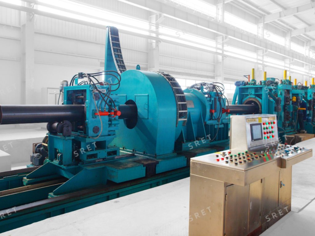
In ERW tube mill lines, cutting finished tubes to precise lengths without stopping the line is a critical operation. The orbital milling type flying cutoff is a next‑generation CNC solution designed specifically for medium and large diameter tubes. Using a milling‑based cutting process, it delivers exceptionally clean, smooth, and burr‑free cut surfaces on every piece.
For detailed specifications and configuration options, see the Orbital Milling Type Flying Cutoff product page.
The cutoff machine is available with two distinct feeding path configurations, each optimised for different tube sizes and shapes in a tube mill line:
Both systems share the same core operating principle, with specific differences in the blade feeding mechanism.
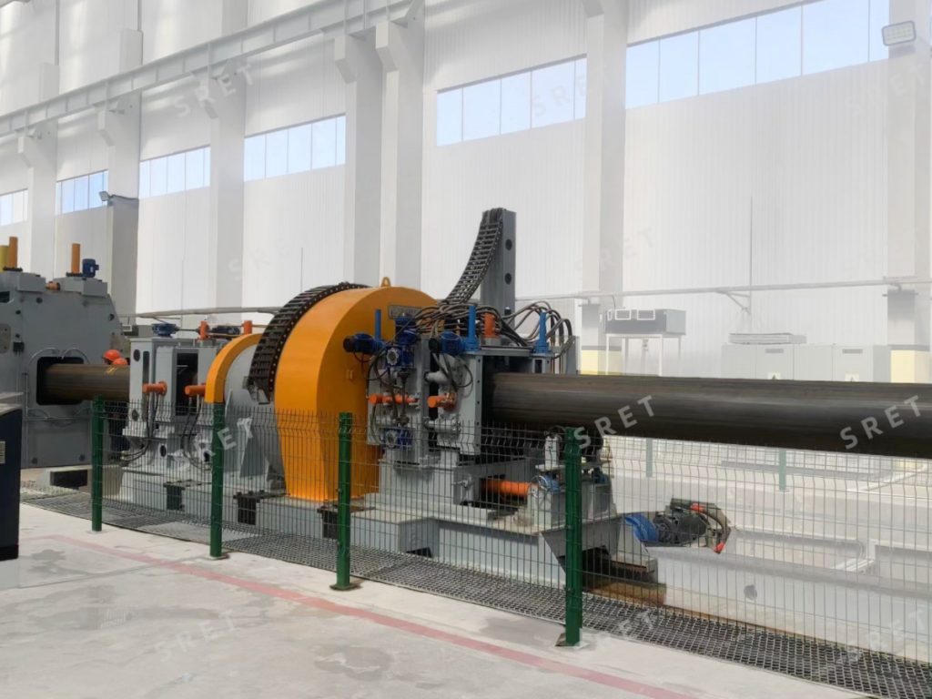 When the tube exits the sizing mill, it passes over a speed measuring roll fitted with a photoelectric encoder. This encoder continuously measures the tube’s speed and length, converting the data into pulse signals transmitted to the motion control system.
The travelling carriage, powered by an AC spindle servo or DC motor via a rack‑and‑pinion mechanism, accelerates to track the moving tube. Once synchronised with the line speed, the hydraulic clamping fixtures on the carriage secure the tube firmly.
The two saw blades, mounted on a rotating table, are driven by spindle servo motors and a custom‑designed reducer. Their feeding motion is a compound movement of:
Guided by ball screws and linear guide mechanisms driven by servo motors, this polar coordinate profiling enables a precise cross‑section milling cut.
Upon completion of the cut:
The entire sequence—carriage acceleration, synchronous tracking, clamping, cutting, and rapid return—is fully automated via a reliable numeric motion control system. Once programmed, the machine operates in unmanned mode within the ERW tube mill line.
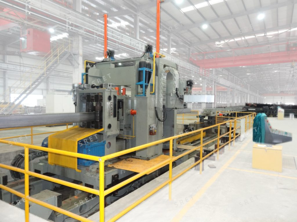
The operating principle is identical to the polar coordinate system, with one key difference: the blade feeding motion follows a rectangular (X‑Y) coordinate path rather than a polar one.
The two saw blades are mounted on sliding tables, and their feeding is a compound movement of:
This movement is also guided by ball screws and linear guide mechanisms driven by servo motors. The rectangular coordinate system is particularly well‑suited for square and rectangular tubes in the 250×250 to 400×400 mm range in a tube mill machine layout.
The rest of the process—speed measurement, carriage tracking, clamping, cutting, return—is identical to the polar coordinate system, ensuring the same high level of automation and precision.
The orbital milling type flying cutoff comprises the following main components:
With hundreds of successful installations worldwide, the milling type flying cut‑off represents an established solution in the ERW tube mill industry. Mature technology minimises investment risk and maximizes operational uptime in tube mill line applications.
Engineered with a rugged mechanical structure, the machine withstands long‑term, heavy‑loaded continuous cutting of various high‑grade materials—day after day—within demanding tube mill machine environments.
Advanced program design enables cutting of round, square, and rectangular tubes with equal precision, supporting flexible production schedules on an ERW tube mill line.
The scientifically designed feeding path and cutting algorithm guarantee:
The system features a graphic‑based HMI interface, providing easy access to:
Once programmed, the cutoff runs completely automatically—reducing labour costs and operator intervention in the tube mill line.
Specially designed hydraulic clamps ensure secure tube holding, directly contributing to cutting accuracy, surface quality, and extended blade life.
Sophisticated programming of S‑curve acceleration/deceleration for the carriage minimizes mechanical shock and prolongs the service life of the transmission mechanism.
An automatic height adjustment system, based on the bottom‑line positioning method, makes specification changeovers quick and convenient on the ERW tube mill machine.
A drawing mechanism pulls the cut tube section forward immediately upon cut‑through, separating the cut seam. This prevents friction between the saw blades and cut faces, further improving blade service life.
Equipped with a remote diagnostic module, the system allows on‑site real‑time status to be assessed from off‑site locations, enabling fast remote troubleshooting and support for tube mill line operators.
Synchronous servo motors are used for blade feeds (both rotary and radial), while spindle motors power the sawing and carriage transmission. This brings:
For optimal performance in a tube mill line, the feeding system is generally selected as follows:
| Tube Shape | Tube Size | Recommended Feeding System |
| Square | 250×250 – 400×400 mm | Rectangular Coordinate |
| Square | Larger than 400×400 mm | Polar Coordinate |
This ensures the most efficient cutting path geometry for your specific product range in an ERW tube mill machine.
The orbital milling type flying cutoff is more than a cutting machine. It is a precision tool that protects tube quality and production efficiency in an ERW tube mill line, similar in function to the shear end welder at the front end of the line. From its heavy‑duty construction and intelligent control to its patented feeding geometry and remote diagnostic capability, every feature is designed to deliver consistent, maintenance‑friendly operation over years of service.
The engineering team brings decades of expertise to every project, offering customized configurations, seamless integration, and responsive after‑sales support for tube mill machine and tube mill line installations.
Technical review: SRET Engineering Team